
X
Click here to view all steps
Don't show me again

Steps
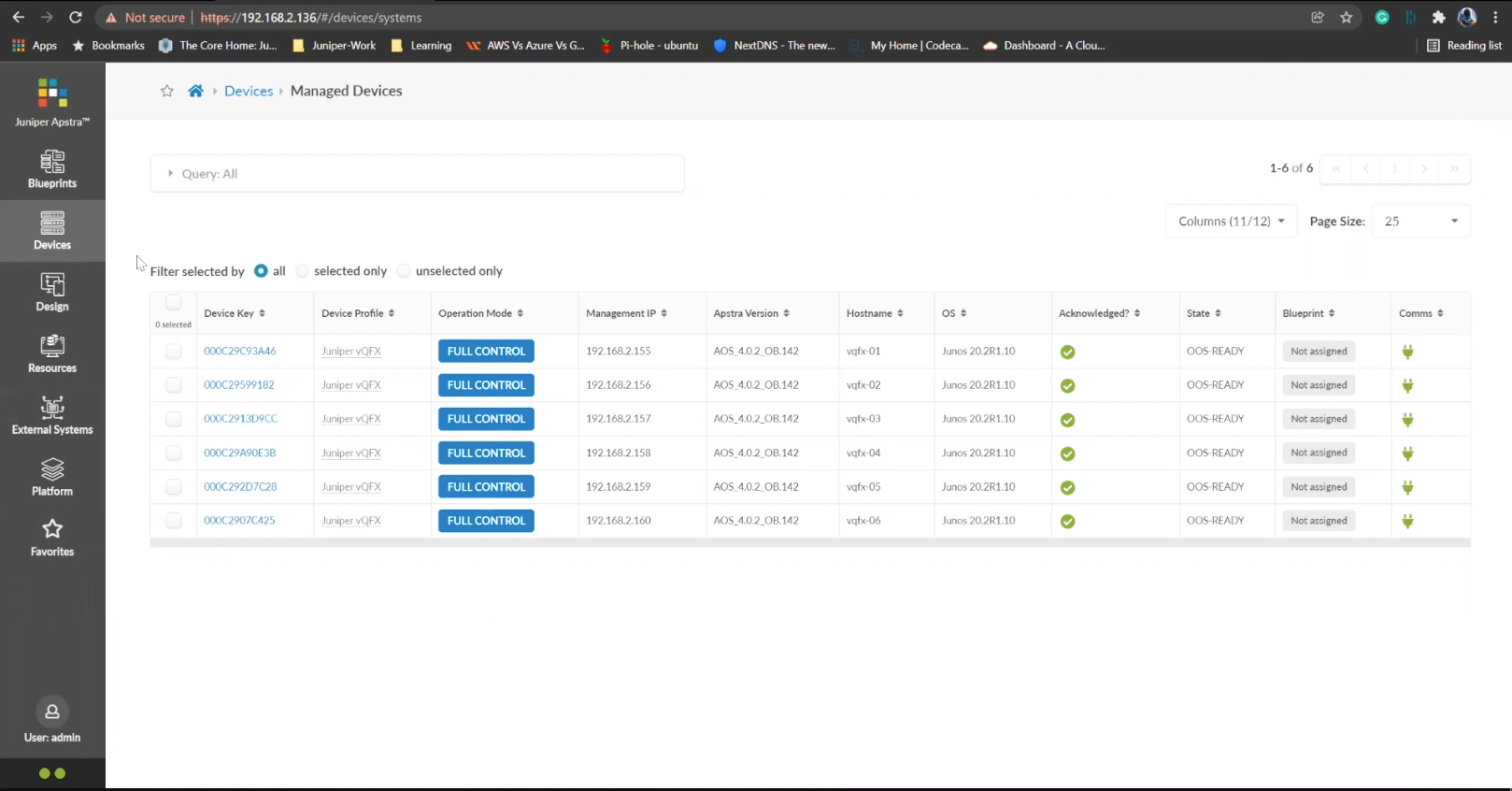
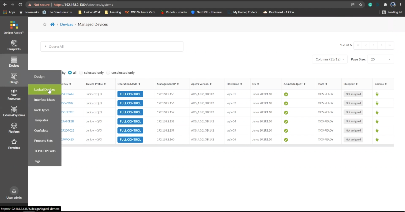
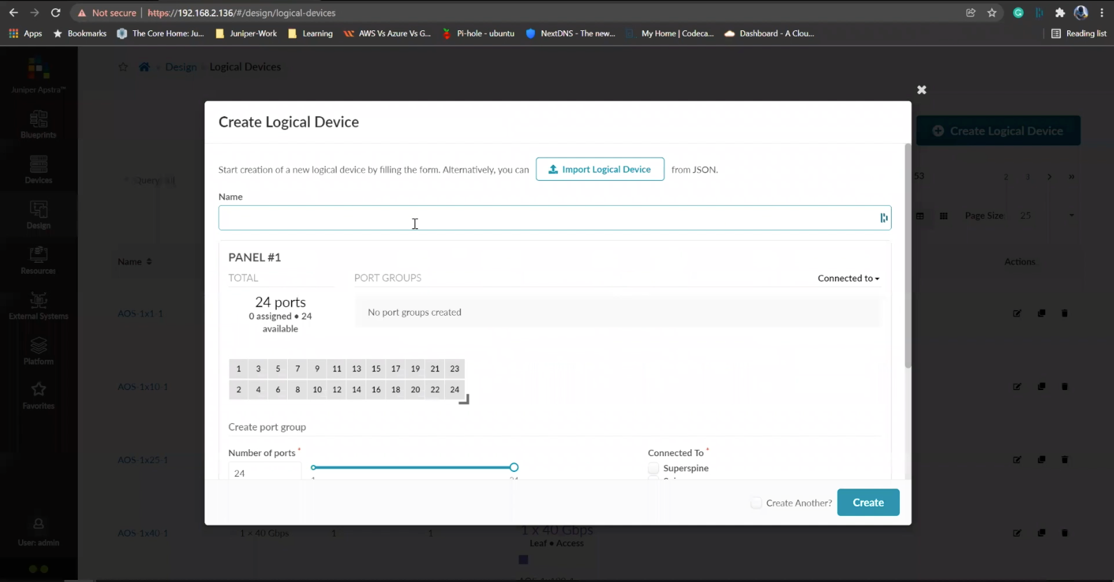
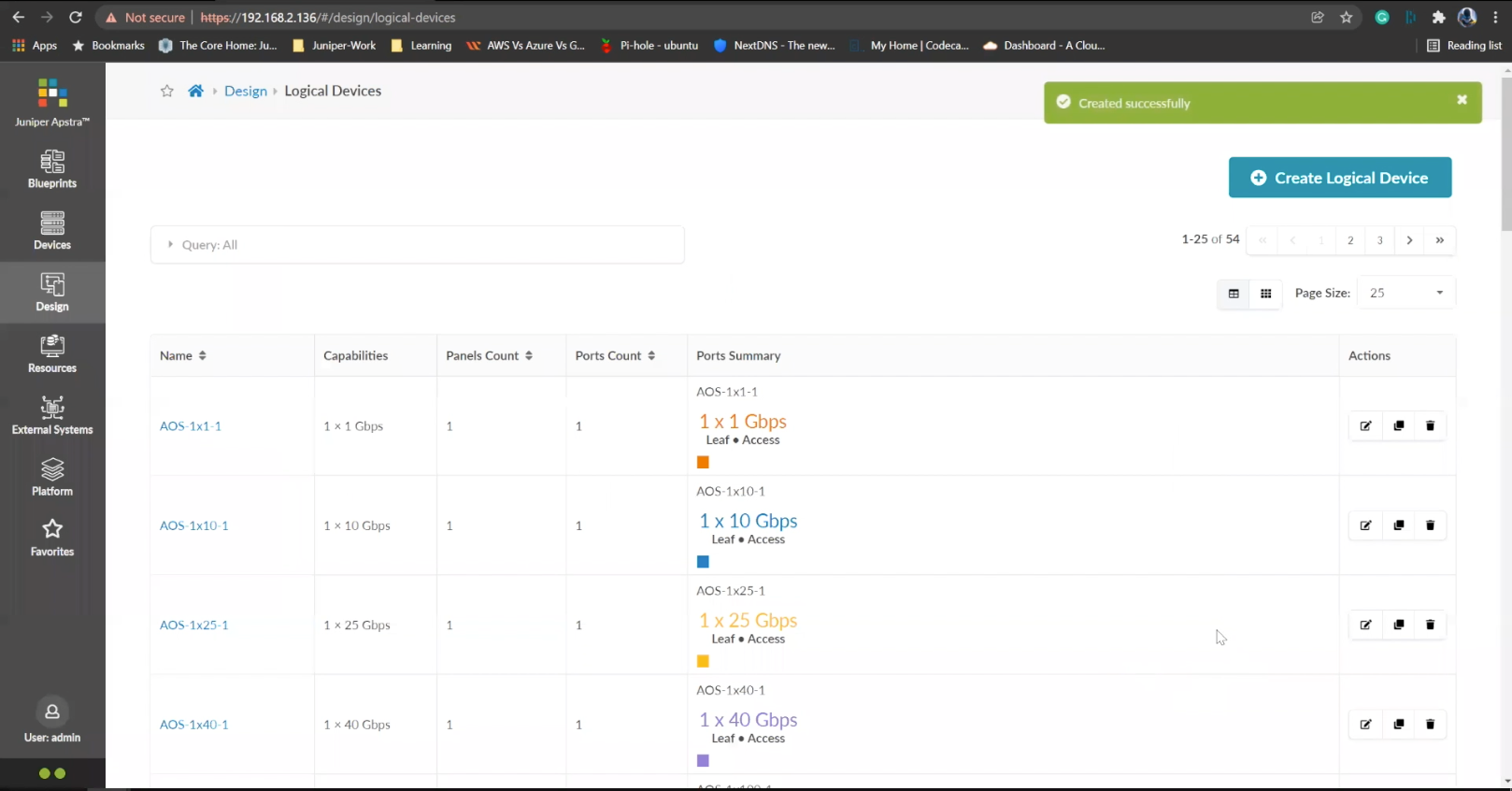
- %3Cp%3EWe%20have%20our%20switches%20already%20managed%20by%20Apstra%2C%20a%20series%20of%20Juniper%20virtual%20QFX%20switches%20in%20this%20example.%20We%20wil%20start%20by%20creating%20logical%20devices.%3C/p%3E
- Click%20on%20logical%20devices%20option%20from%20the%20menu
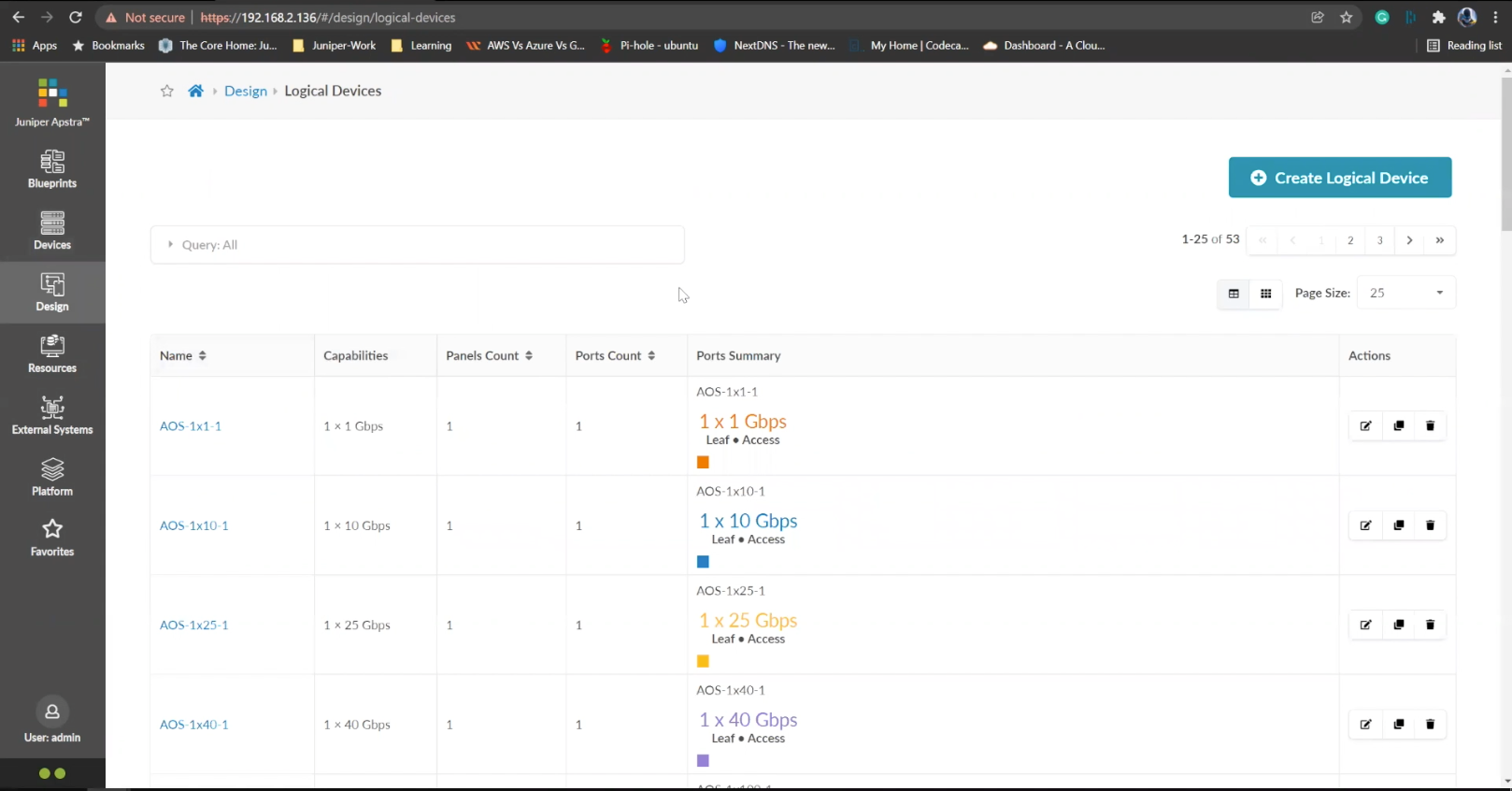
- %3Cp%3E%3Cspan%20style%3D%22font-size%3A%2013px%3B%22%3ETo%20start%20the%20process%2C%20we%20will%20creat%20a%20leaf%20device%20first.%20%3C/span%3E%3C/p%3E%0A%3Cp%3E%3Cspan%20style%3D%22font-size%3A%2015px%3B%22%3EPlease%20Note%3A%20%3C/span%3E%3C/p%3E%0A%3Cp%3E%3Cspan%20style%3D%22font-size%3A%2013px%3B%22%3EThe%20same%20process%20can%20be%20replicated%20for%20a%20spine%20logical%20device%20too.%20For%20the%20purpose%20of%20this%20demo%2C%20we%20will%20skip%20the%20spine%20logical%20device%20creation%20process.%3C/span%3E%3C/p%3E
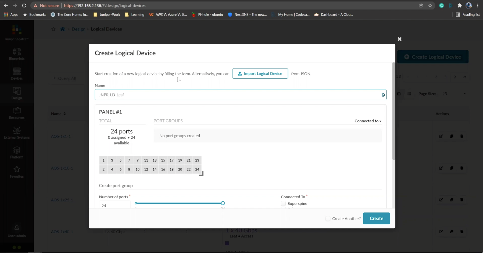
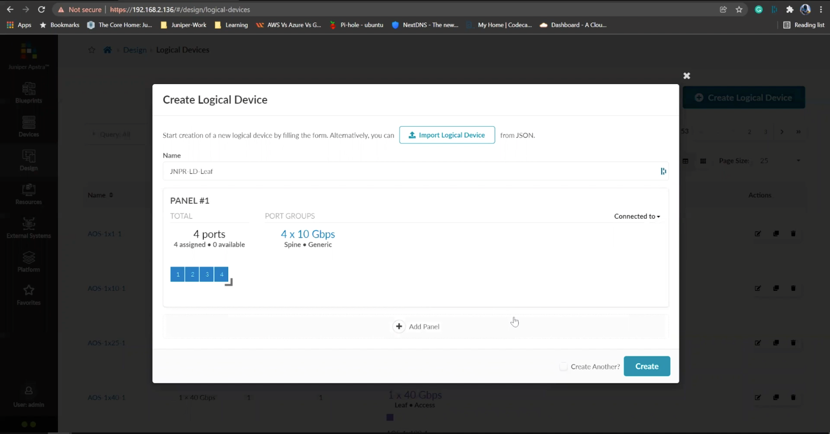
- Enter a name for the logical device
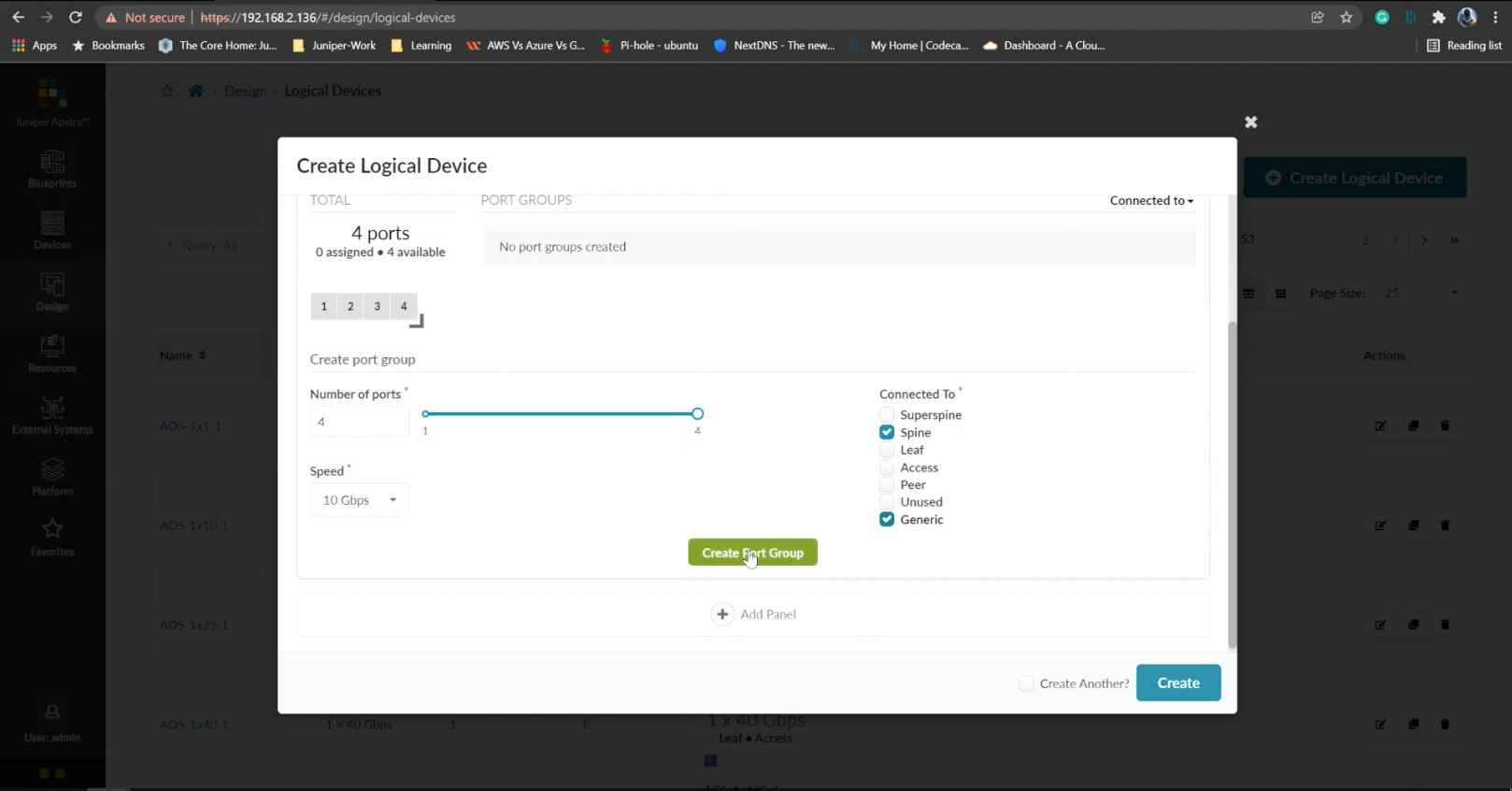
- Choose the number of ports
- Create a port group
- Click to finish the creation
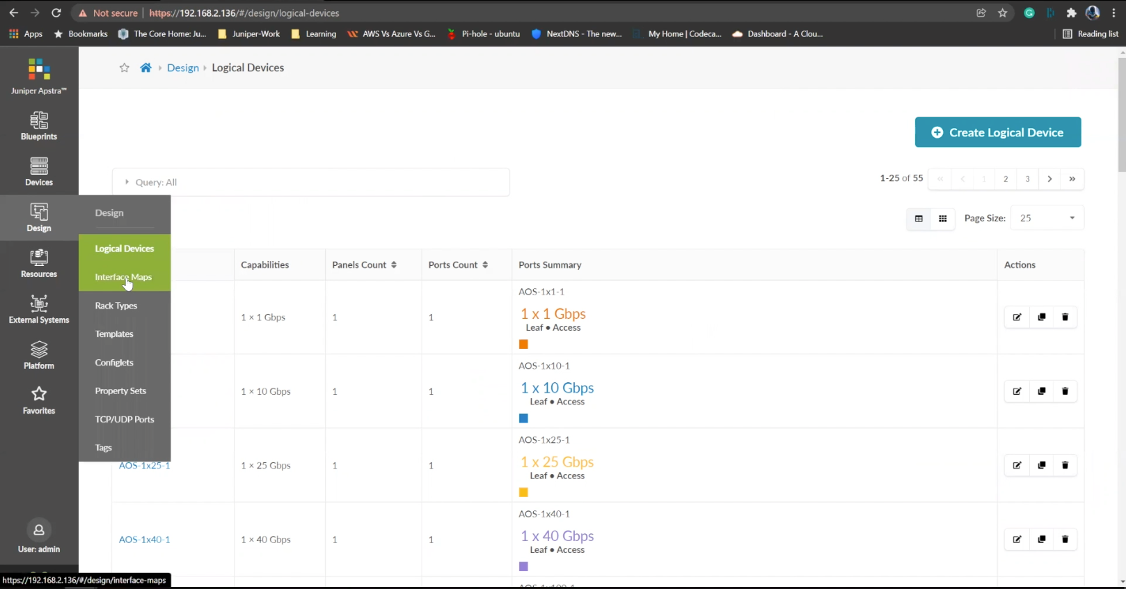
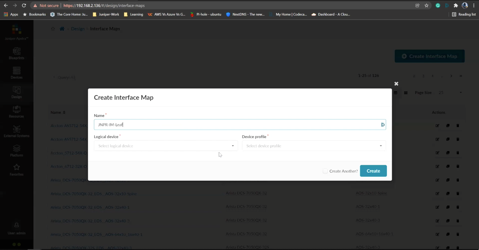
- %3Cp%3E%3Cspan%20style%3D%22font-size%3A%2013px%3B%22%3E%3Cspan%20style%3D%22font-family%3A%20Calibri%2C%20sans-serif%3B%22%3ENext%20we%20will%20set%20up%20interface%20maps.%20An%20Interface%20map%20maps%20the%20logical%20device%20to%20the%20actual%20physical%20device.%20ie%3A%20a%20specific%20switch%20and%20model%20that%20is%20used%20in%20the%20actual%20typology.%3C/span%3E%3C/span%3E%3C/p%3E
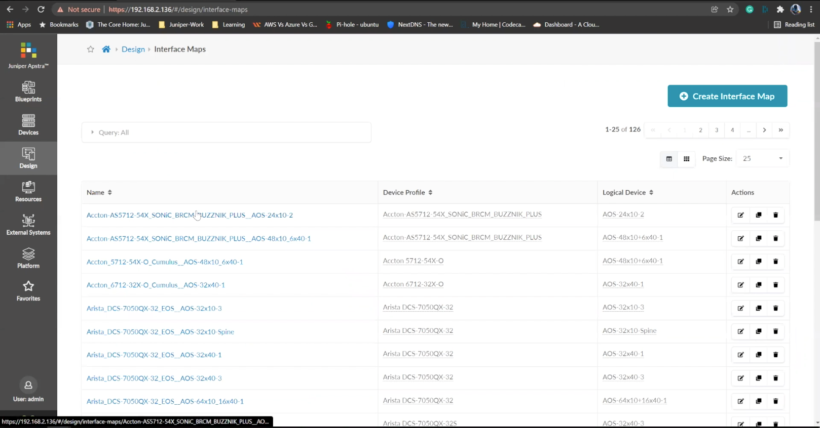
- Click on the Interface maps option from the menu
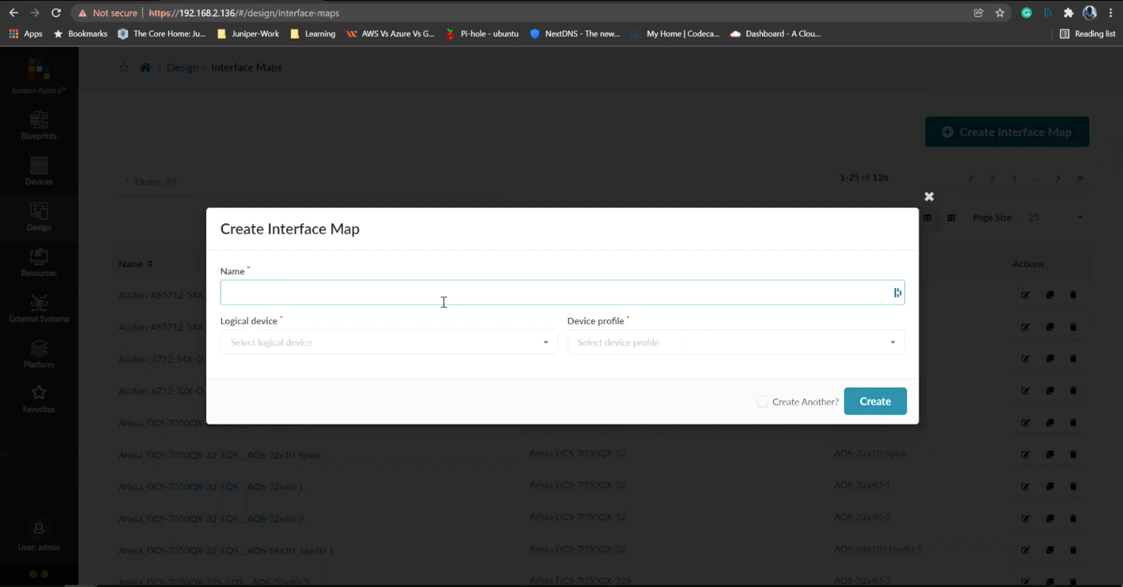
- Click to create a new interface map
- Add a name
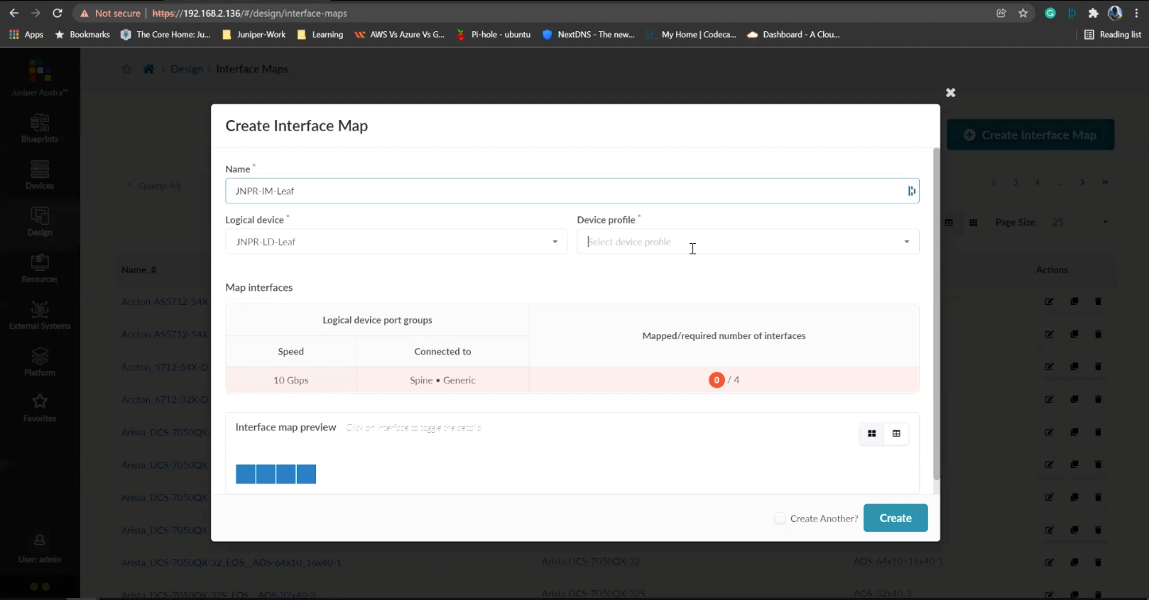
- Choose a logical device that will be mapped to a physical entity
- Choose from the drop down list
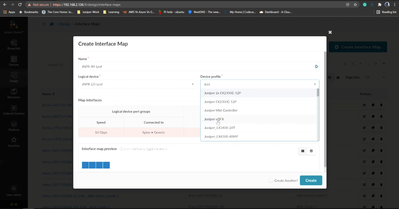
- Choose a device profile from the drop down menu
- Choose the Juniper QFX device as shown
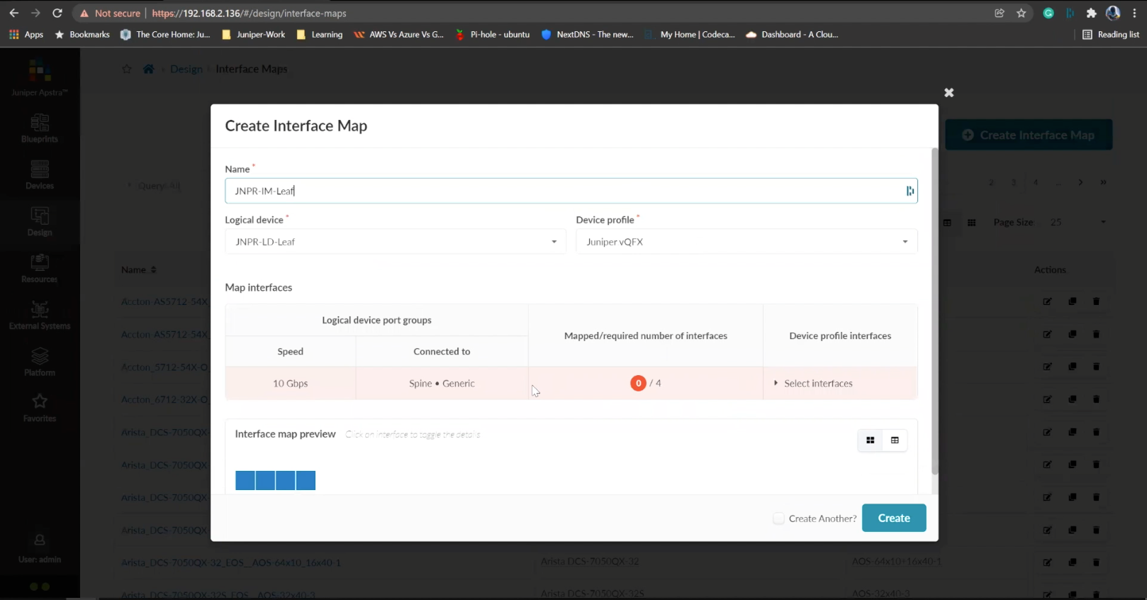
- Choose the interfaces
- %3Cp%3E%3Cspan%20style%3D%22font-size%3A%2013px%3B%22%3EWe%20will%20repeat%20the%20same%20process%20for%20the%20spine%20devices%20defined%20earlier.%20We%20will%20be%20mapping%20it%20to%20the%20Juniper%20QFX%20devices%20as%20well.%3C/span%3E%3C/p%3E
- Next we will add a few racks
- Click on the rack type from the menu
- Click to create a rack type
- Add a name for the new rack
- Name the leaf switch
- Choose a logical leaf device that was previously defined
- Choose the desired logical device from the list
- Click to add a new Generic system
- Add a name to the Generic System Group
- Enter a desired name
- FInish the process of creating a new rack
- Let us add another generic system
- Click to edit the rack type
- Navigate to the leafs tab
- Click on generic systems tab
- Up the Generic system count to 2 and then update the rack type
- Bring everything together in the next steps
- Choose templates from the menu
- Click to create a template
- Add a name first
- Enter more details and then scroll down
- To choose a rack type click on the drop down menu
- Choose the rack type that we created earlier from the menu
- Click to select the desired spine logical device
- Choose the logical spine device from the list
- Enter the desired count
- Click on create to complete the configuration
- Next step is to create a blueprint for the entire Datacenter fabric
- Click to create a new blueprint
- Enter a name for the Blueprint
- Choose the template from the drop down menu
- Choose the desired template
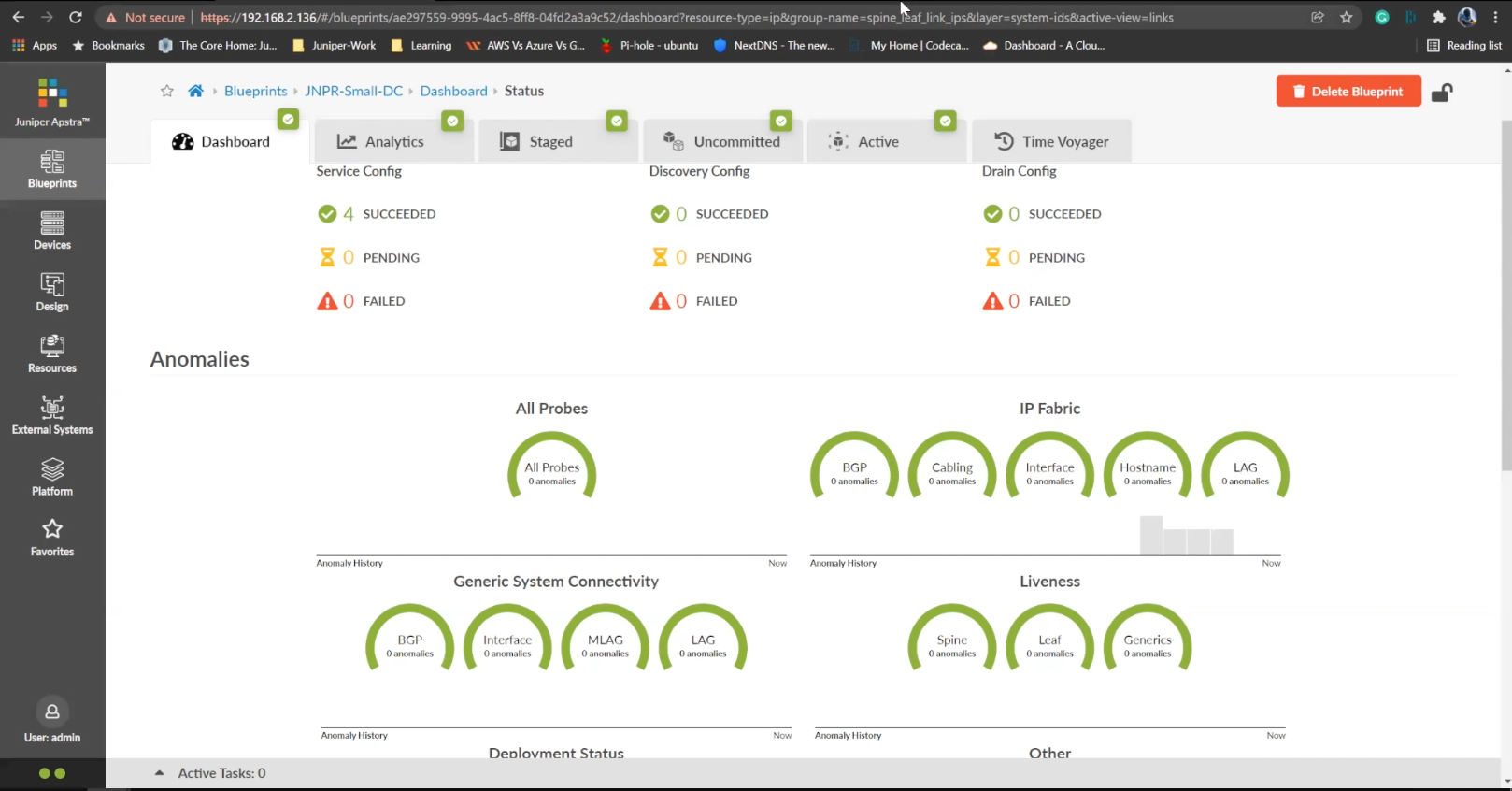
- Click to display the links
- Click on create to finish the process
- Click to view the Blueprint
- Click on staged
- Select the spines to allocate an Autonomous ID
- Click on the edit icon
- Choose the IP address from the Pool
- Save the configuration
- Repeat the same process for the other leaf devices
- Next we need to configure the interface mappings
- Click on one of the spine devices
- Click on the edit icon
- Choose the interface mappings from the the drop down menu
- Make the desired selection
- Click to update the assignments
- Click to assign system IDs next
- Click on the Assigned System IDs tab
- Click on the edit icon
- Choose from the list of System IDs
- Finalize the assignments
- Click on links
- Recitify any cabling errors as shown automatically
- Update the cabling assingments
- Notice the success message once the cabling mapping is sorted out
- Click on commit
- Add the description and click on the commit button
- Success
Steps
- %3Cp%3EWe%20have%20our%20switches%20already%20managed%20by%20Apstra%2C%20a%20series%20of%20Juniper%20virtual%20QFX%20switches%20in%20this%20example.%20We%20wil%20start%20by%20creating%20logical%20devices.%3C/p%3E
- Click%20on%20logical%20devices%20option%20from%20the%20menu
- %3Cp%3E%3Cspan%20style%3D%22font-size%3A%2013px%3B%22%3ETo%20start%20the%20process%2C%20we%20will%20creat%20a%20leaf%20device%20first.%20%3C/span%3E%3C/p%3E%0A%3Cp%3E%3Cspan%20style%3D%22font-size%3A%2015px%3B%22%3EPlease%20Note%3A%20%3C/span%3E%3C/p%3E%0A%3Cp%3E%3Cspan%20style%3D%22font-size%3A%2013px%3B%22%3EThe%20same%20process%20can%20be%20replicated%20for%20a%20spine%20logical%20device%20too.%20For%20the%20purpose%20of%20this%20demo%2C%20we%20will%20skip%20the%20spine%20logical%20device%20creation%20process.%3C/span%3E%3C/p%3E
- Enter a name for the logical device
- Choose the number of ports
- Create a port group
- Click to finish the creation
- %3Cp%3E%3Cspan%20style%3D%22font-size%3A%2013px%3B%22%3E%3Cspan%20style%3D%22font-family%3A%20Calibri%2C%20sans-serif%3B%22%3ENext%20we%20will%20set%20up%20interface%20maps.%20An%20Interface%20map%20maps%20the%20logical%20device%20to%20the%20actual%20physical%20device.%20ie%3A%20a%20specific%20switch%20and%20model%20that%20is%20used%20in%20the%20actual%20typology.%3C/span%3E%3C/span%3E%3C/p%3E
- Click on the Interface maps option from the menu
- Click to create a new interface map
- Add a name
- Choose a logical device that will be mapped to a physical entity
- Choose from the drop down list
- Choose a device profile from the drop down menu
- Choose the Juniper QFX device as shown
- Choose the interfaces
- %3Cp%3E%3Cspan%20style%3D%22font-size%3A%2013px%3B%22%3EWe%20will%20repeat%20the%20same%20process%20for%20the%20spine%20devices%20defined%20earlier.%20We%20will%20be%20mapping%20it%20to%20the%20Juniper%20QFX%20devices%20as%20well.%3C/span%3E%3C/p%3E
- Next we will add a few racks
- Click on the rack type from the menu
- Click to create a rack type
- Add a name for the new rack
- Name the leaf switch
- Choose a logical leaf device that was previously defined
- Choose the desired logical device from the list
- Click to add a new Generic system
- Add a name to the Generic System Group
- Enter a desired name
- FInish the process of creating a new rack
- Let us add another generic system
- Click to edit the rack type
- Navigate to the leafs tab
- Click on generic systems tab
- Up the Generic system count to 2 and then update the rack type
- Bring everything together in the next steps
- Choose templates from the menu
- Click to create a template
- Add a name first
- Enter more details and then scroll down
- To choose a rack type click on the drop down menu
- Choose the rack type that we created earlier from the menu
- Click to select the desired spine logical device
- Choose the logical spine device from the list
- Enter the desired count
- Click on create to complete the configuration
- Next step is to create a blueprint for the entire Datacenter fabric
- Click to create a new blueprint
- Enter a name for the Blueprint
- Choose the template from the drop down menu
- Choose the desired template
- Click to display the links
- Click on create to finish the process
- Click to view the Blueprint
- Click on staged
- Select the spines to allocate an Autonomous ID
- Click on the edit icon
- Choose the IP address from the Pool
- Save the configuration
- Repeat the same process for the other leaf devices
- Next we need to configure the interface mappings
- Click on one of the spine devices
- Click on the edit icon
- Choose the interface mappings from the the drop down menu
- Make the desired selection
- Click to update the assignments
- Click to assign system IDs next
- Click on the Assigned System IDs tab
- Click on the edit icon
- Choose from the list of System IDs
- Finalize the assignments
- Click on links
- Recitify any cabling errors as shown automatically
- Update the cabling assingments
- Notice the success message once the cabling mapping is sorted out
- Click on commit
- Add the description and click on the commit button
- Success
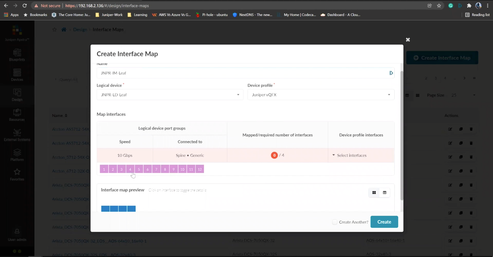
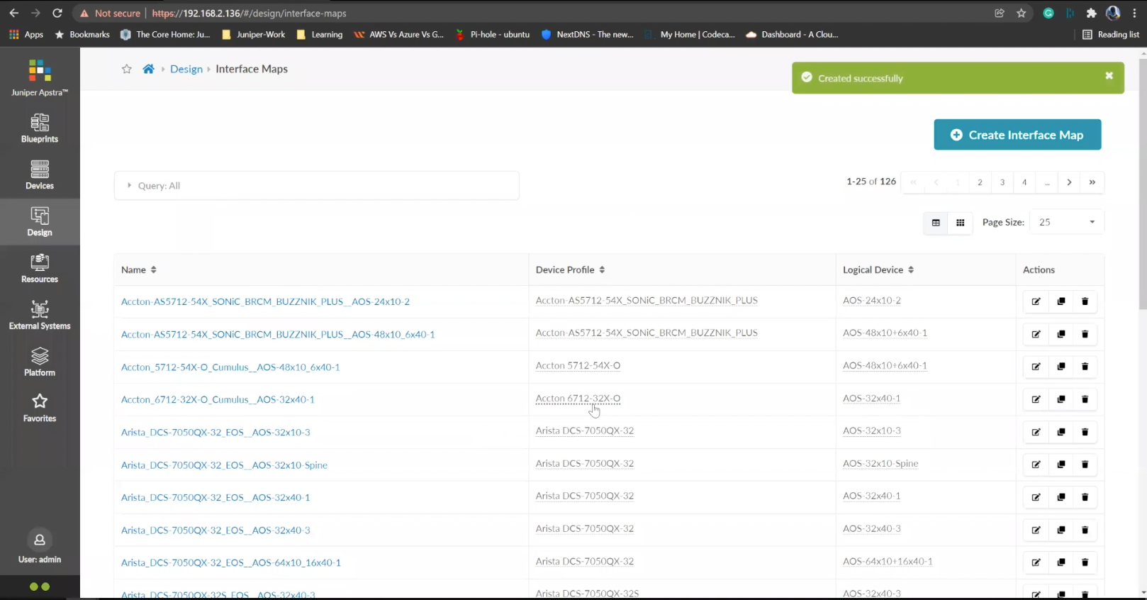
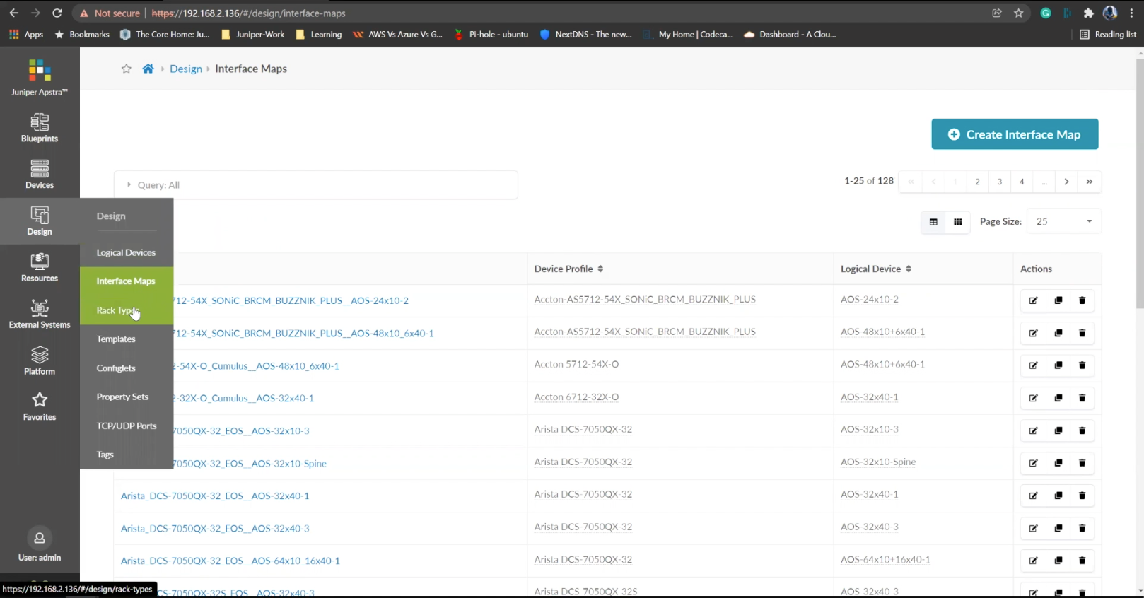
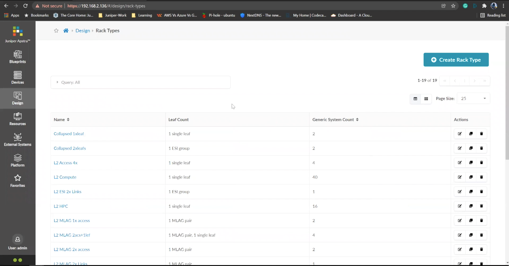
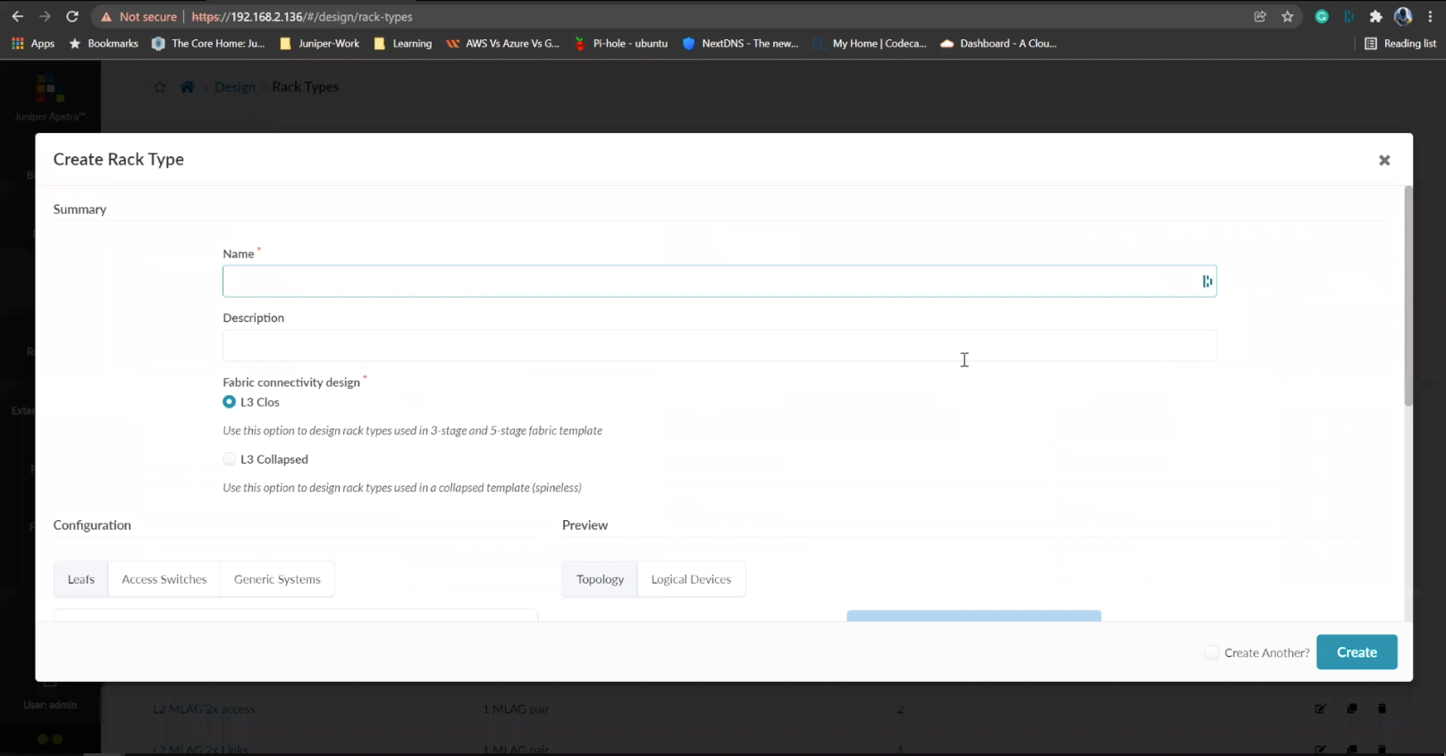
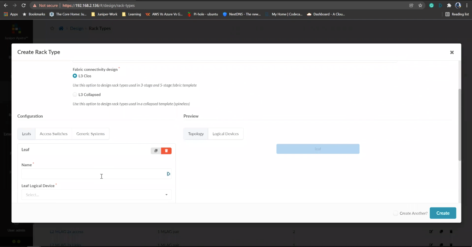
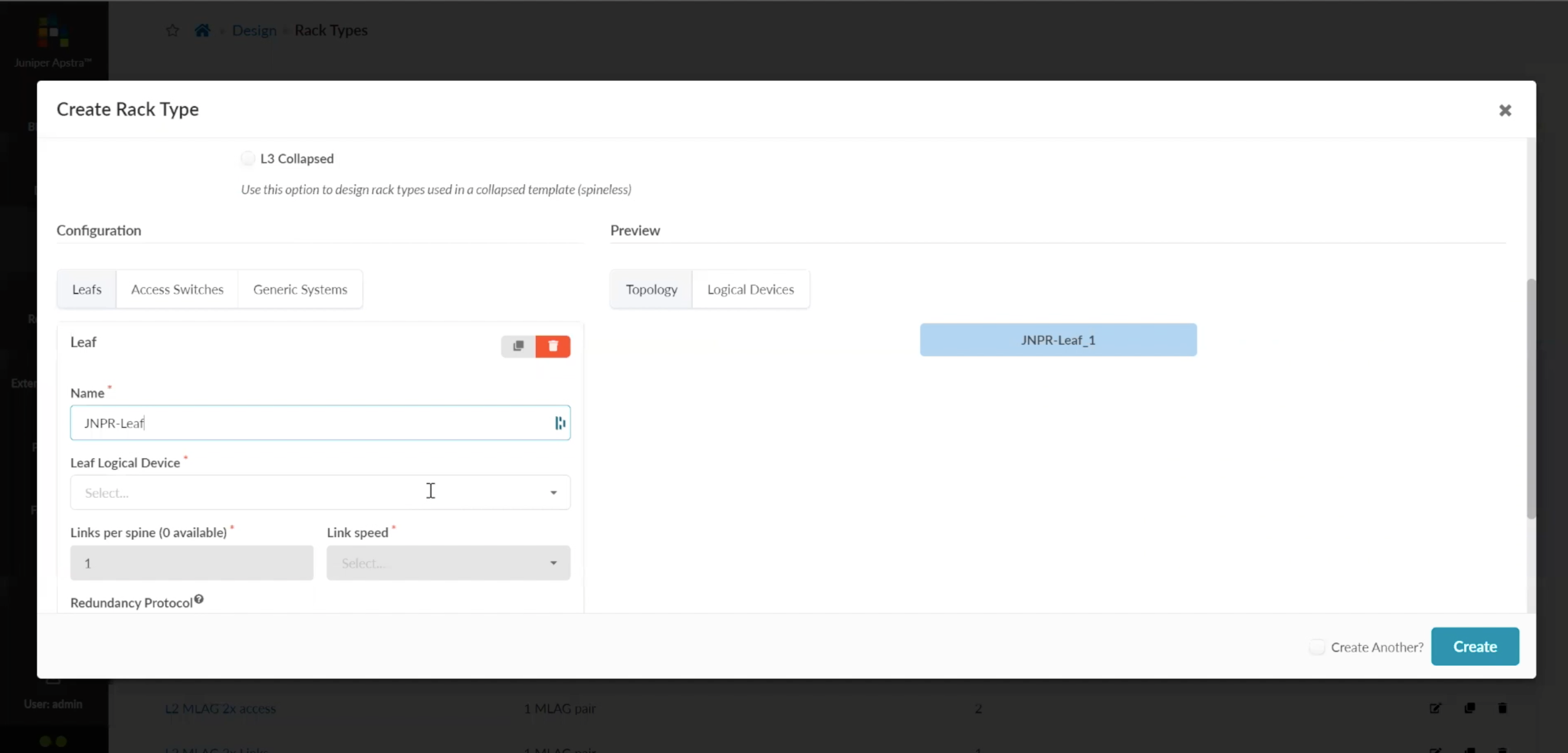
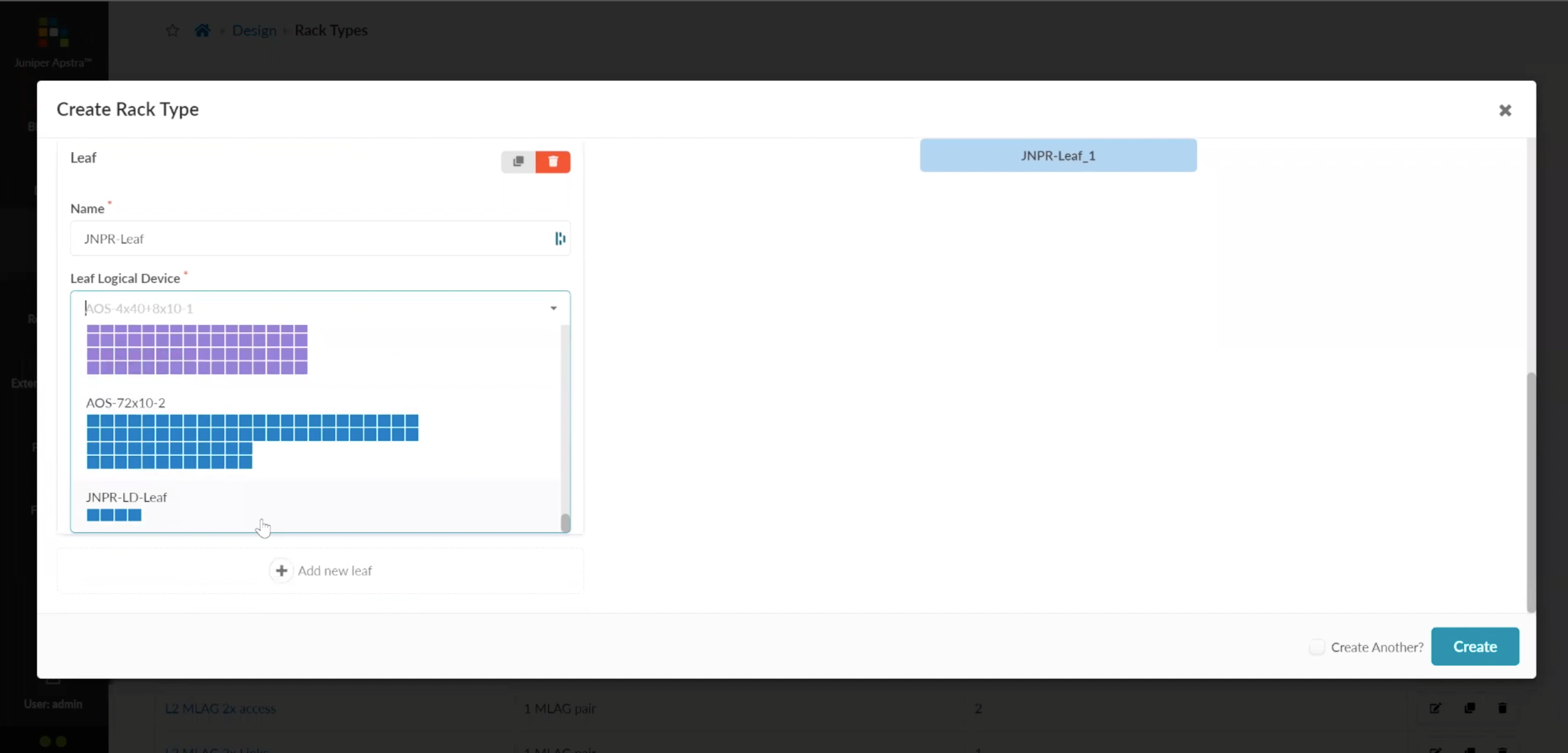
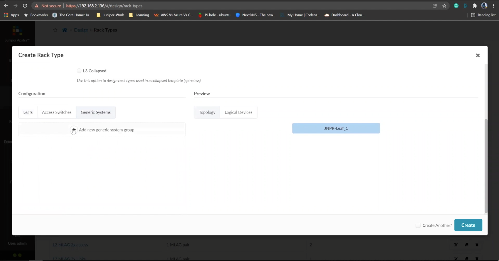
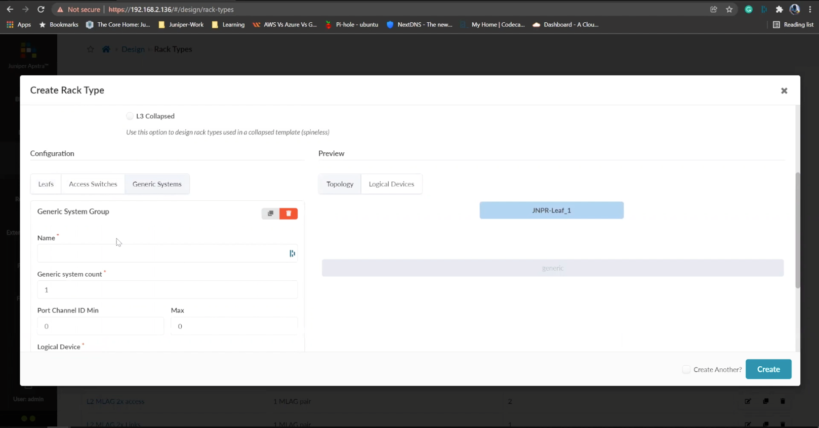
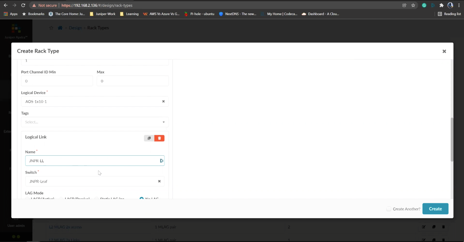
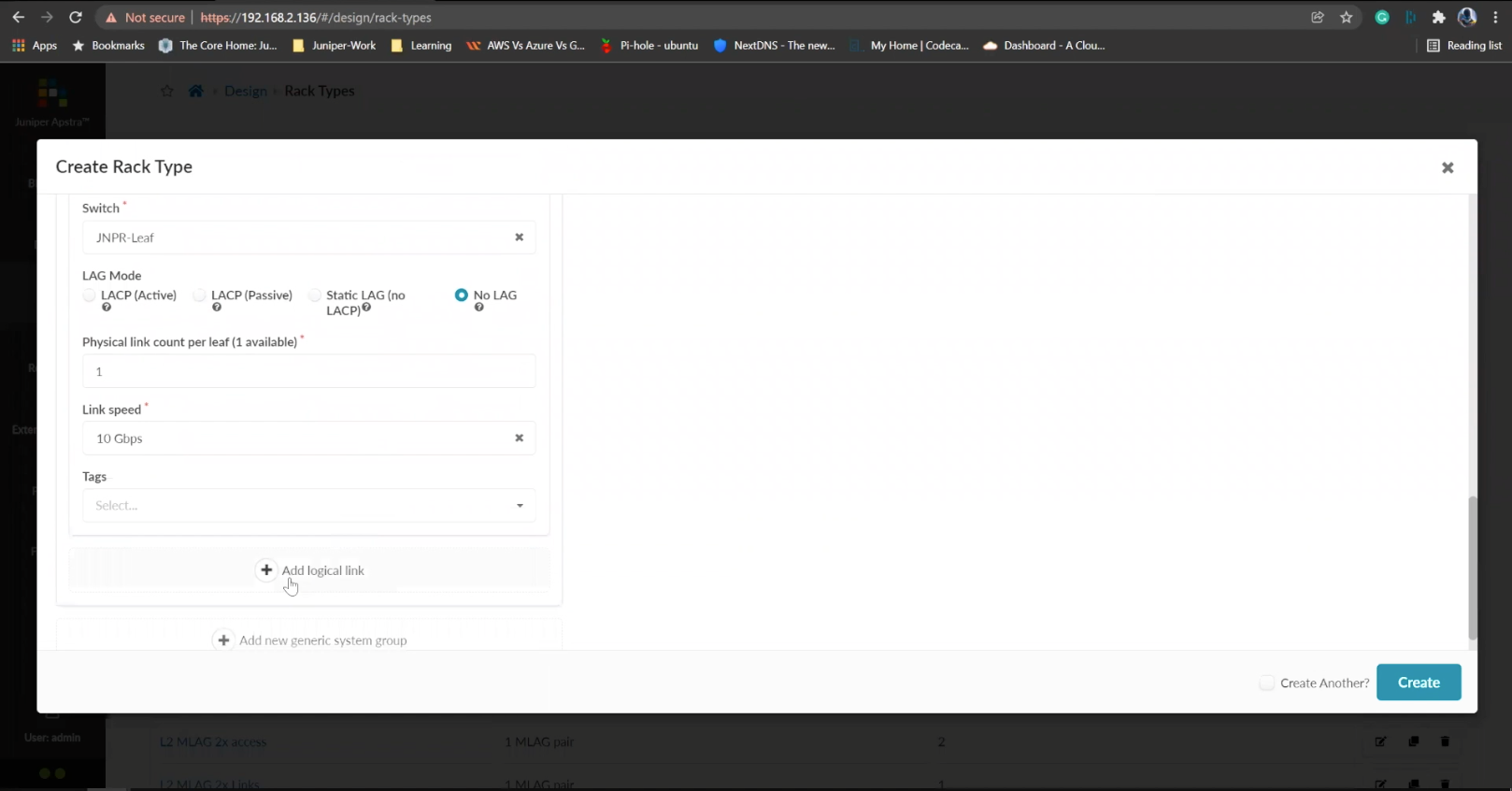
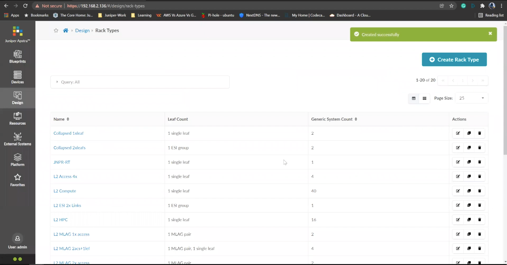
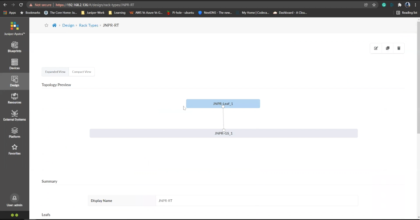
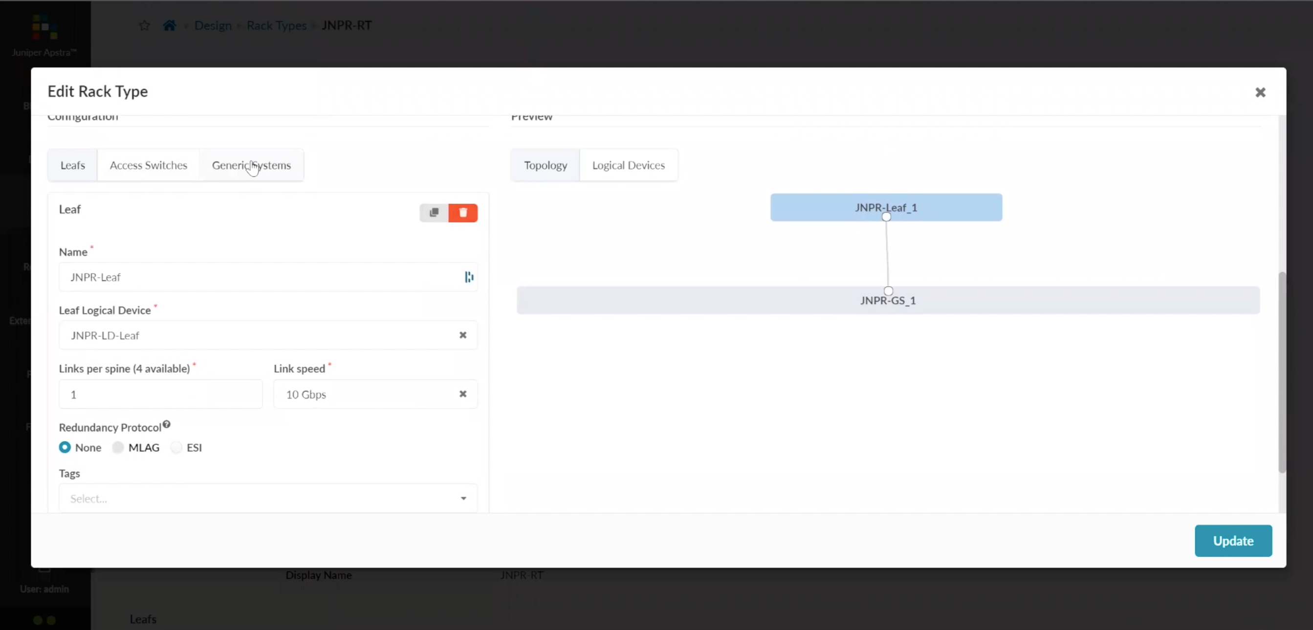
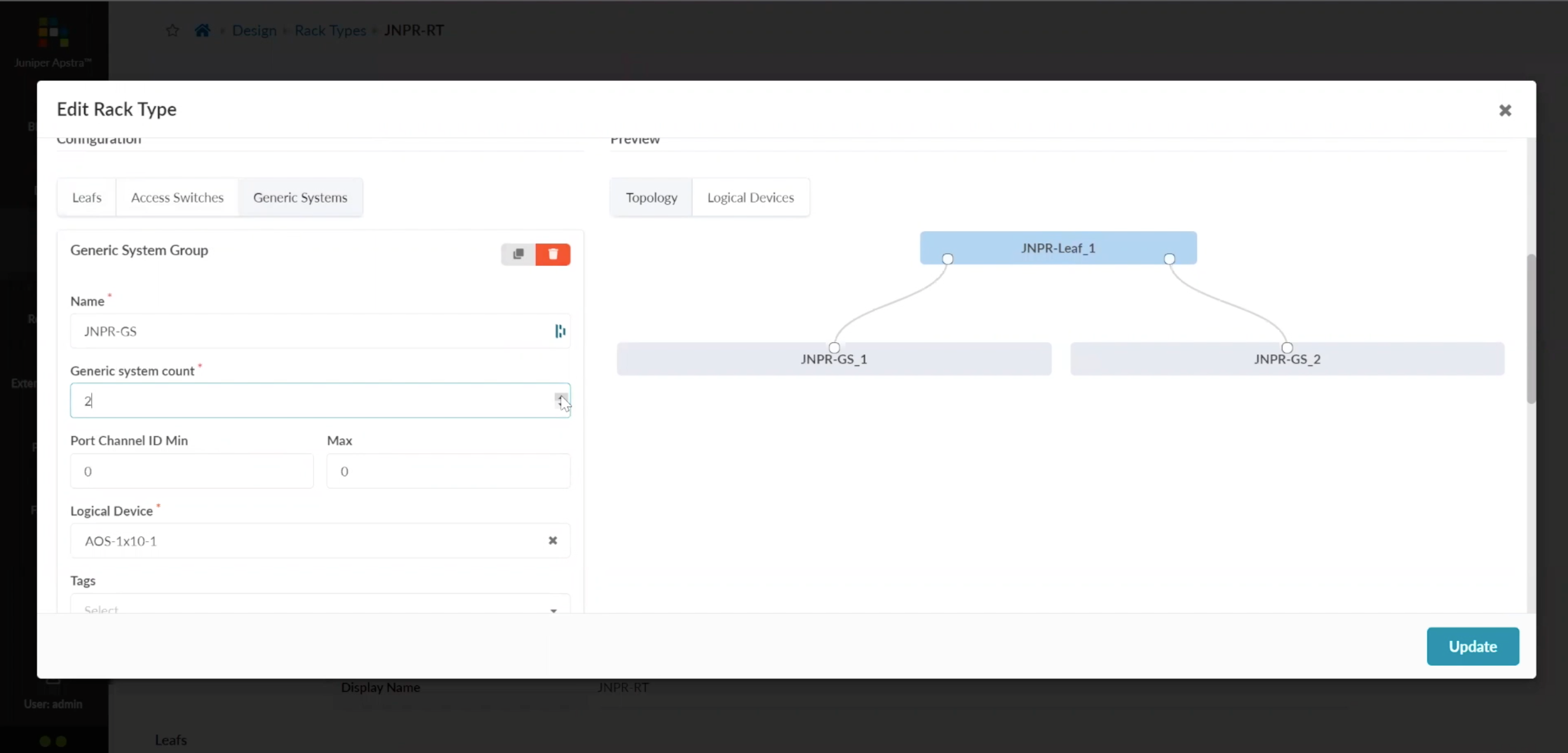
1
Up the system count from 1 to 2
Steps
- %3Cp%3EWe%20have%20our%20switches%20already%20managed%20by%20Apstra%2C%20a%20series%20of%20Juniper%20virtual%20QFX%20switches%20in%20this%20example.%20We%20wil%20start%20by%20creating%20logical%20devices.%3C/p%3E
- Click%20on%20logical%20devices%20option%20from%20the%20menu
- %3Cp%3E%3Cspan%20style%3D%22font-size%3A%2013px%3B%22%3ETo%20start%20the%20process%2C%20we%20will%20creat%20a%20leaf%20device%20first.%20%3C/span%3E%3C/p%3E%0A%3Cp%3E%3Cspan%20style%3D%22font-size%3A%2015px%3B%22%3EPlease%20Note%3A%20%3C/span%3E%3C/p%3E%0A%3Cp%3E%3Cspan%20style%3D%22font-size%3A%2013px%3B%22%3EThe%20same%20process%20can%20be%20replicated%20for%20a%20spine%20logical%20device%20too.%20For%20the%20purpose%20of%20this%20demo%2C%20we%20will%20skip%20the%20spine%20logical%20device%20creation%20process.%3C/span%3E%3C/p%3E
- Enter a name for the logical device
- Choose the number of ports
- Create a port group
- Click to finish the creation
- %3Cp%3E%3Cspan%20style%3D%22font-size%3A%2013px%3B%22%3E%3Cspan%20style%3D%22font-family%3A%20Calibri%2C%20sans-serif%3B%22%3ENext%20we%20will%20set%20up%20interface%20maps.%20An%20Interface%20map%20maps%20the%20logical%20device%20to%20the%20actual%20physical%20device.%20ie%3A%20a%20specific%20switch%20and%20model%20that%20is%20used%20in%20the%20actual%20typology.%3C/span%3E%3C/span%3E%3C/p%3E
- Click on the Interface maps option from the menu
- Click to create a new interface map
- Add a name
- Choose a logical device that will be mapped to a physical entity
- Choose from the drop down list
- Choose a device profile from the drop down menu
- Choose the Juniper QFX device as shown
- Choose the interfaces
- %3Cp%3E%3Cspan%20style%3D%22font-size%3A%2013px%3B%22%3EWe%20will%20repeat%20the%20same%20process%20for%20the%20spine%20devices%20defined%20earlier.%20We%20will%20be%20mapping%20it%20to%20the%20Juniper%20QFX%20devices%20as%20well.%3C/span%3E%3C/p%3E
- Next we will add a few racks
- Click on the rack type from the menu
- Click to create a rack type
- Add a name for the new rack
- Name the leaf switch
- Choose a logical leaf device that was previously defined
- Choose the desired logical device from the list
- Click to add a new Generic system
- Add a name to the Generic System Group
- Enter a desired name
- FInish the process of creating a new rack
- Let us add another generic system
- Click to edit the rack type
- Navigate to the leafs tab
- Click on generic systems tab
- Up the Generic system count to 2 and then update the rack type
- Bring everything together in the next steps
- Choose templates from the menu
- Click to create a template
- Add a name first
- Enter more details and then scroll down
- To choose a rack type click on the drop down menu
- Choose the rack type that we created earlier from the menu
- Click to select the desired spine logical device
- Choose the logical spine device from the list
- Enter the desired count
- Click on create to complete the configuration
- Next step is to create a blueprint for the entire Datacenter fabric
- Click to create a new blueprint
- Enter a name for the Blueprint
- Choose the template from the drop down menu
- Choose the desired template
- Click to display the links
- Click on create to finish the process
- Click to view the Blueprint
- Click on staged
- Select the spines to allocate an Autonomous ID
- Click on the edit icon
- Choose the IP address from the Pool
- Save the configuration
- Repeat the same process for the other leaf devices
- Next we need to configure the interface mappings
- Click on one of the spine devices
- Click on the edit icon
- Choose the interface mappings from the the drop down menu
- Make the desired selection
- Click to update the assignments
- Click to assign system IDs next
- Click on the Assigned System IDs tab
- Click on the edit icon
- Choose from the list of System IDs
- Finalize the assignments
- Click on links
- Recitify any cabling errors as shown automatically
- Update the cabling assingments
- Notice the success message once the cabling mapping is sorted out
- Click on commit
- Add the description and click on the commit button
- Success
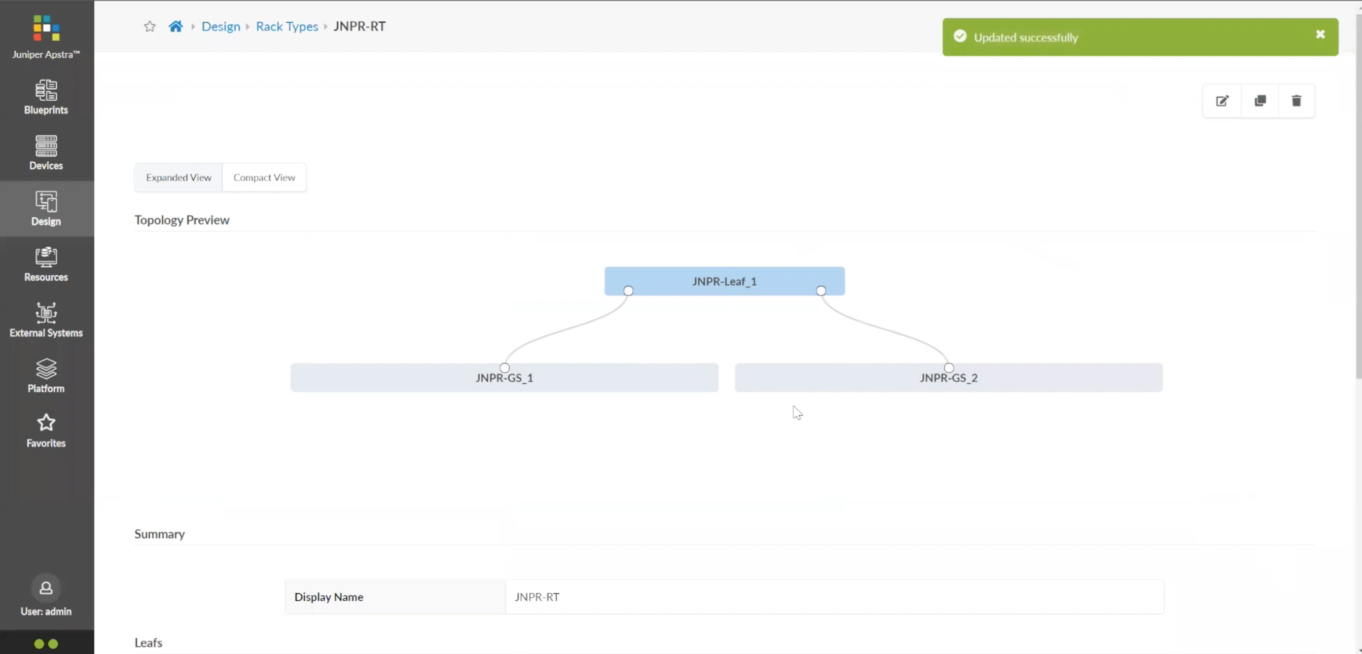
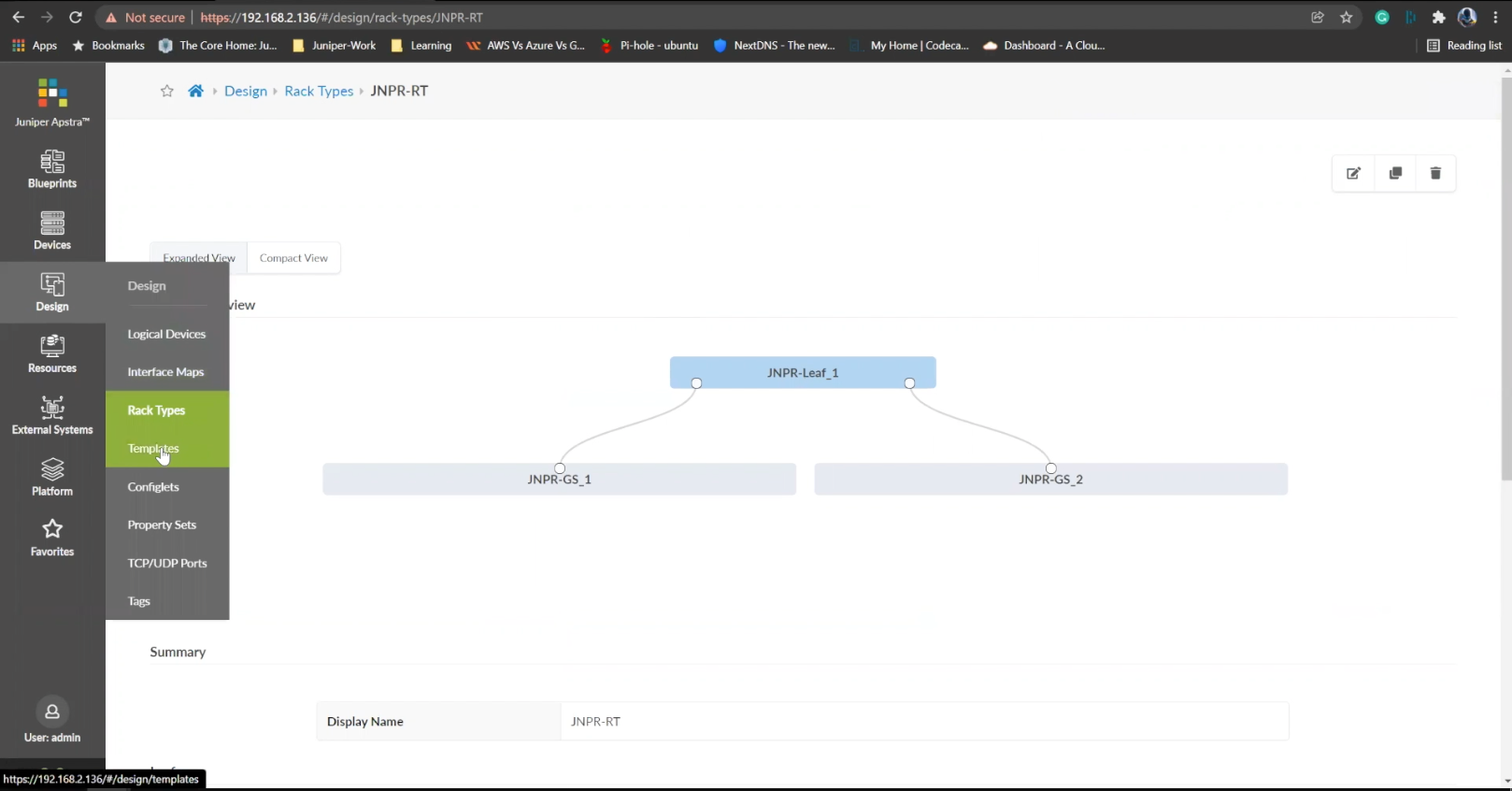
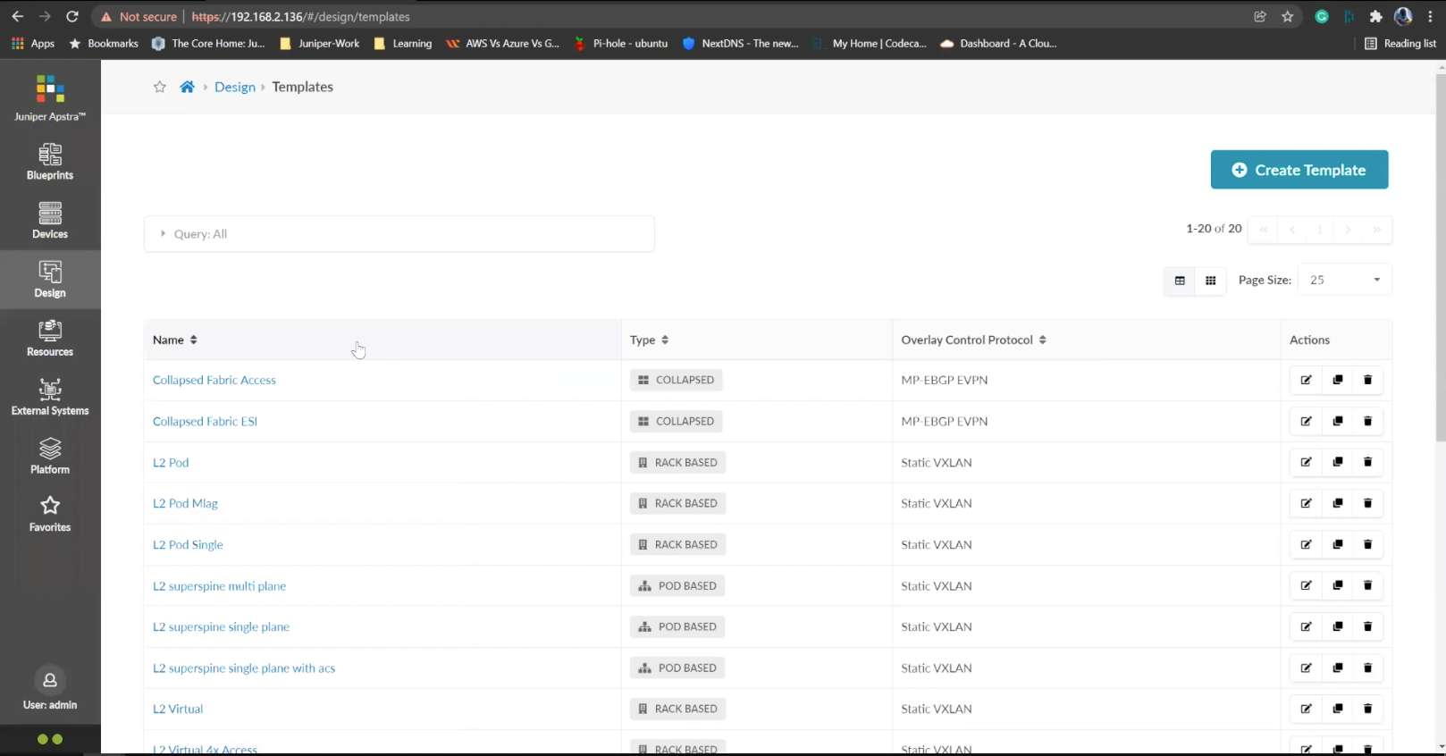
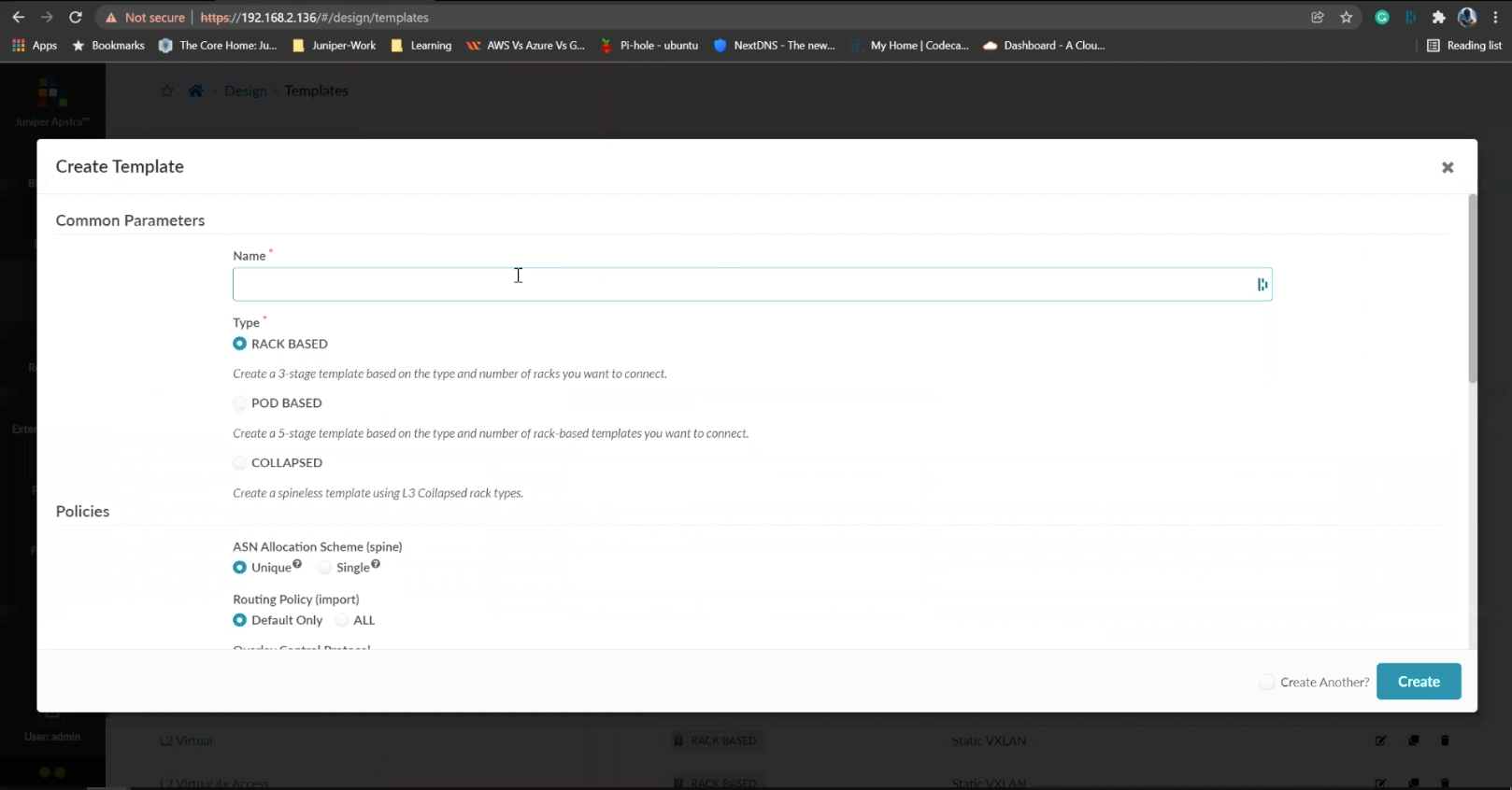
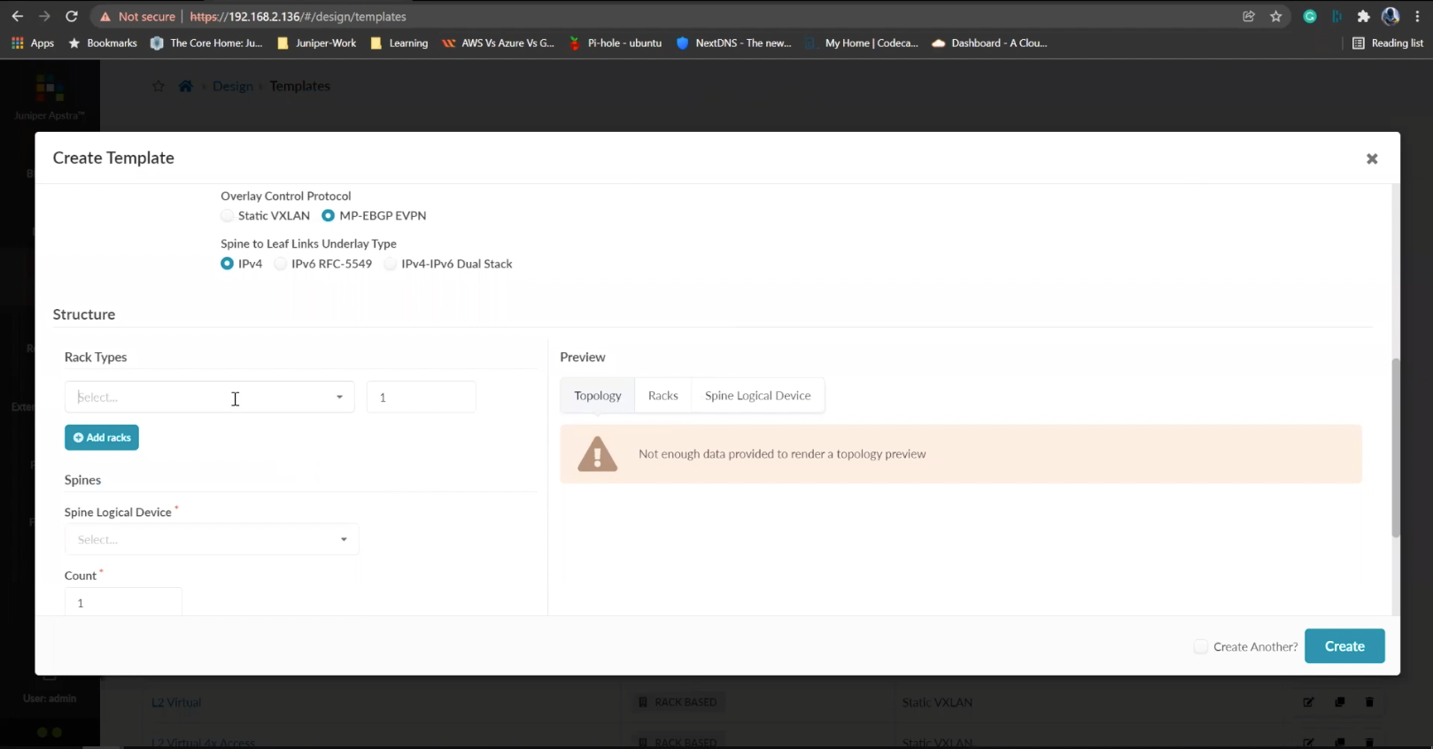
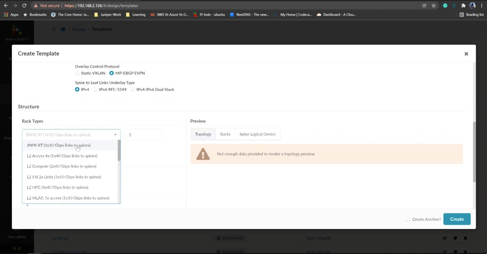
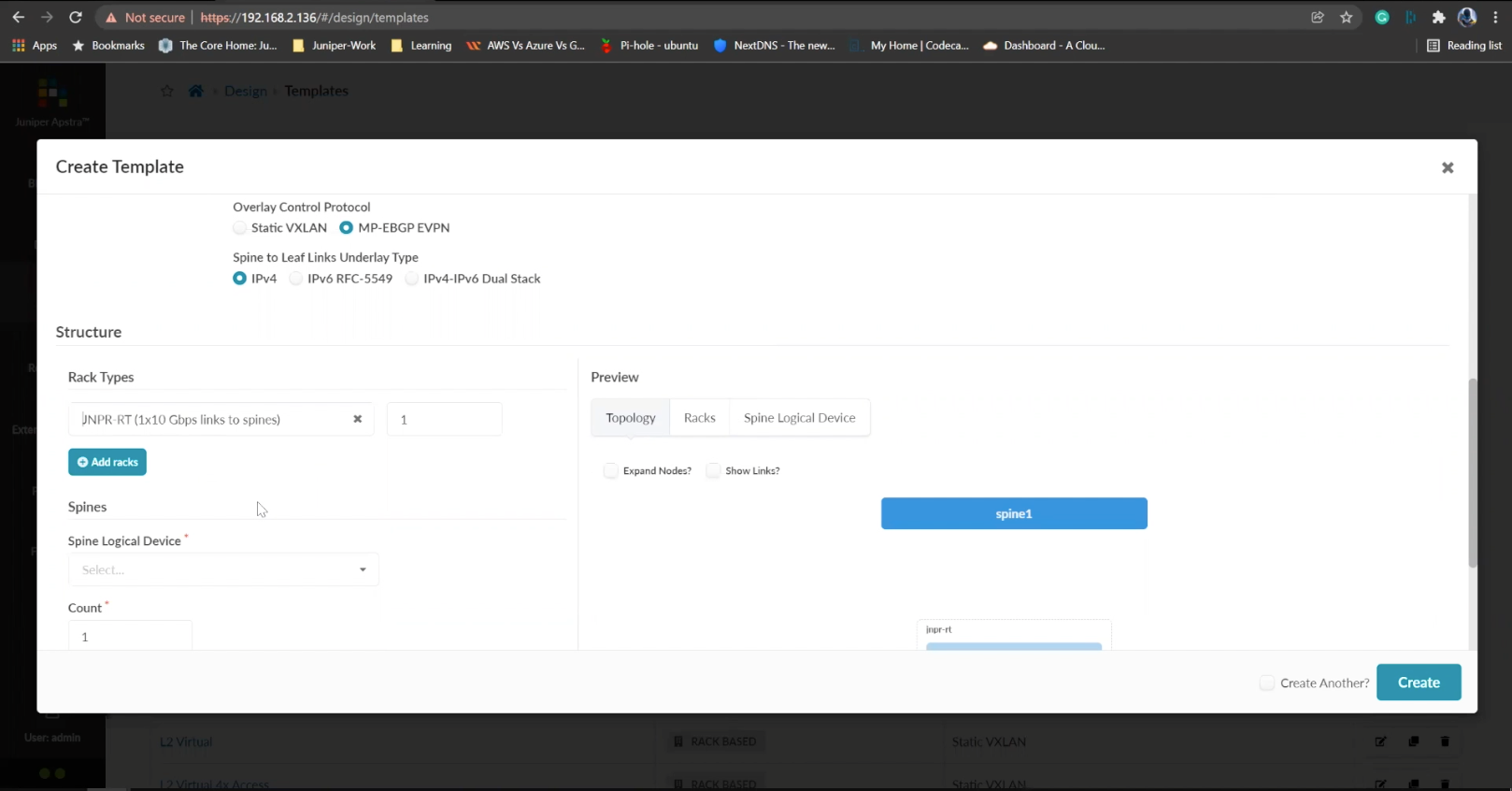
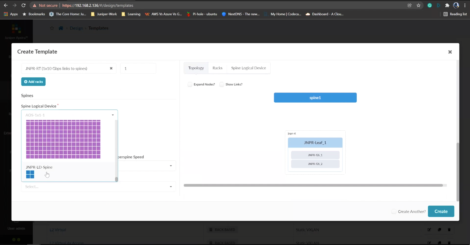
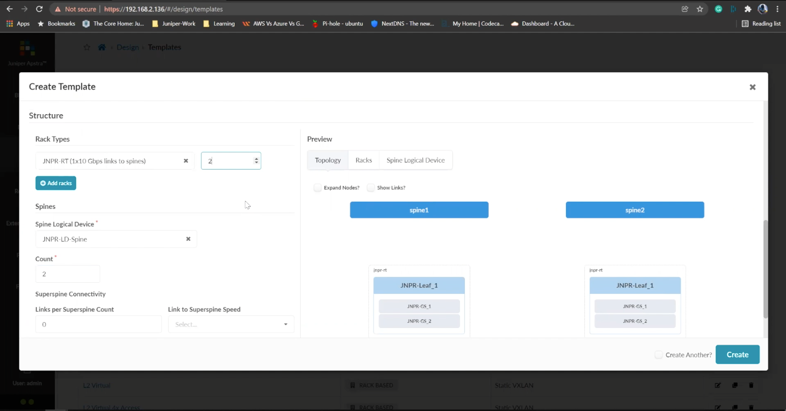
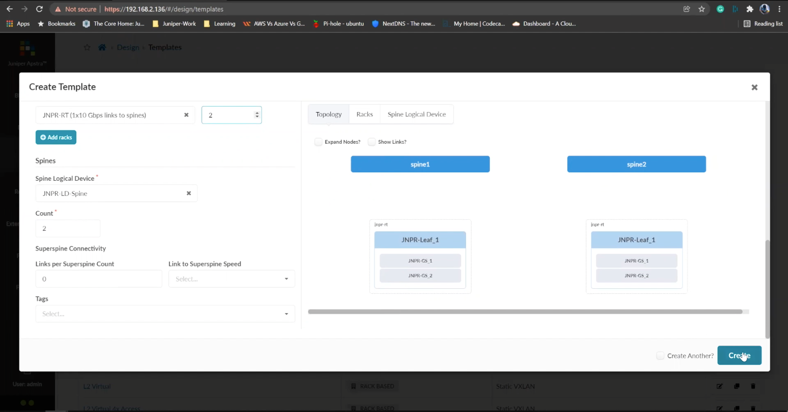
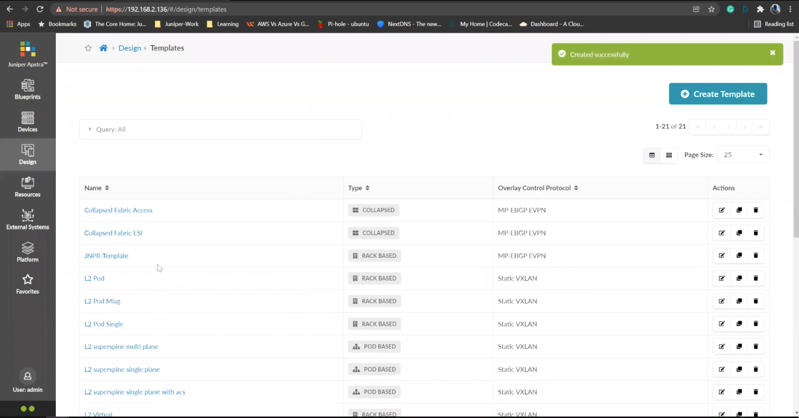
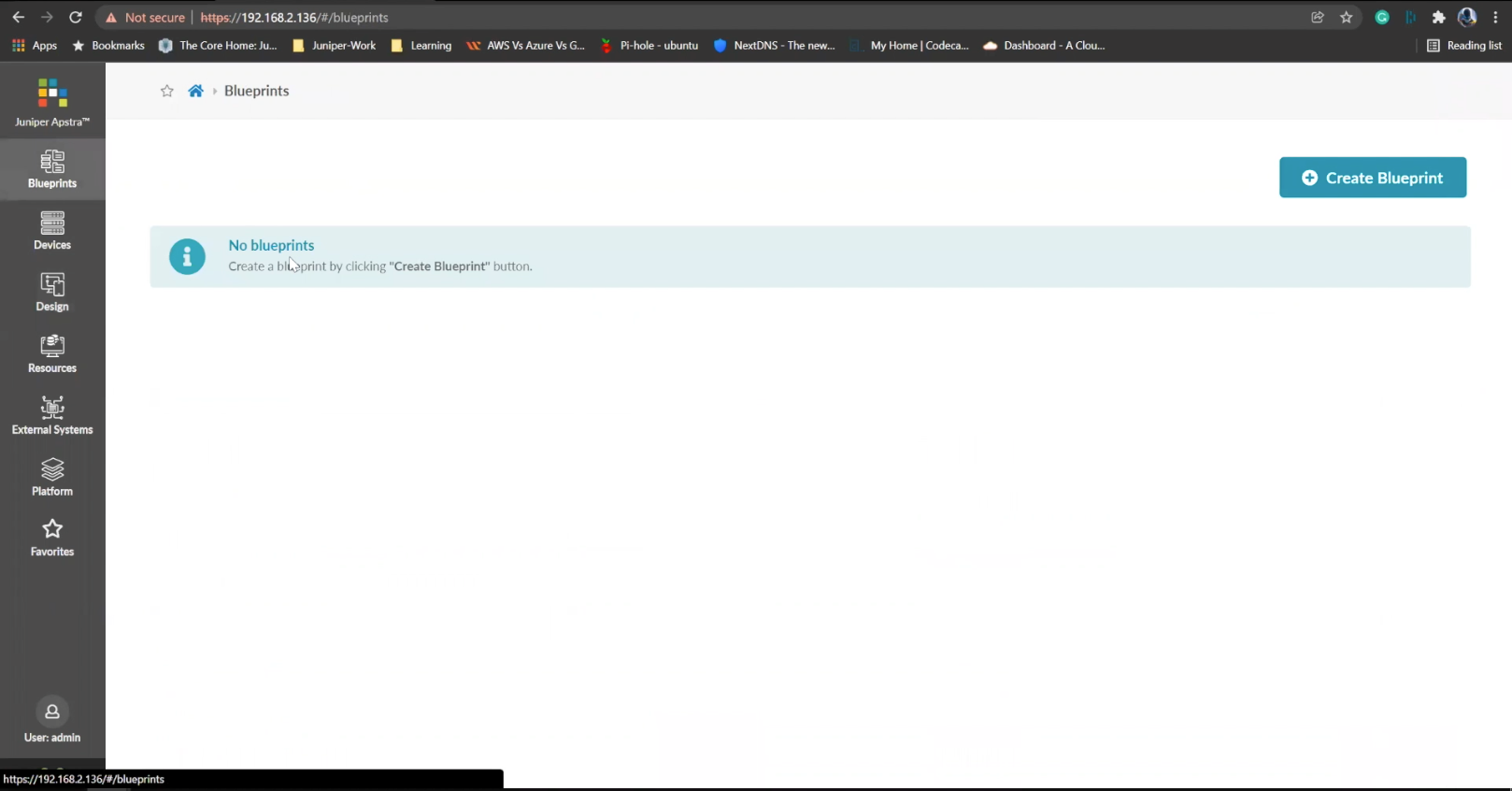
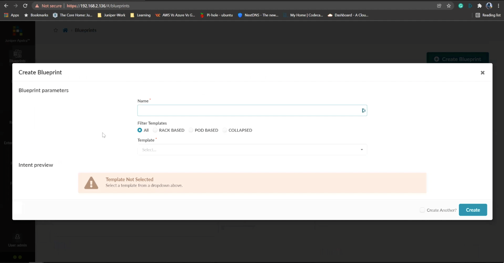
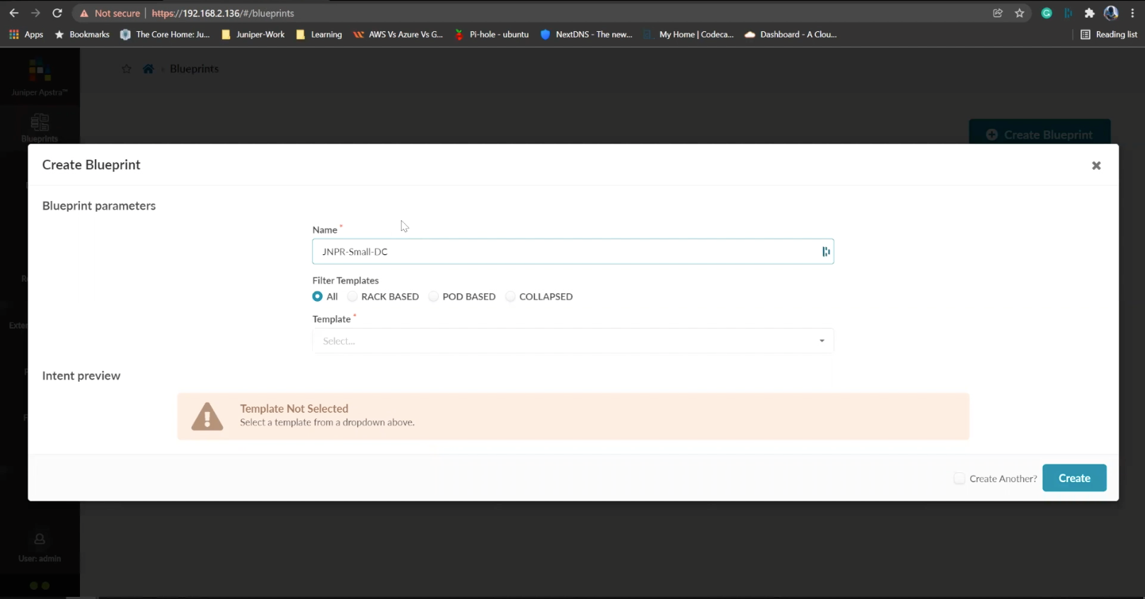
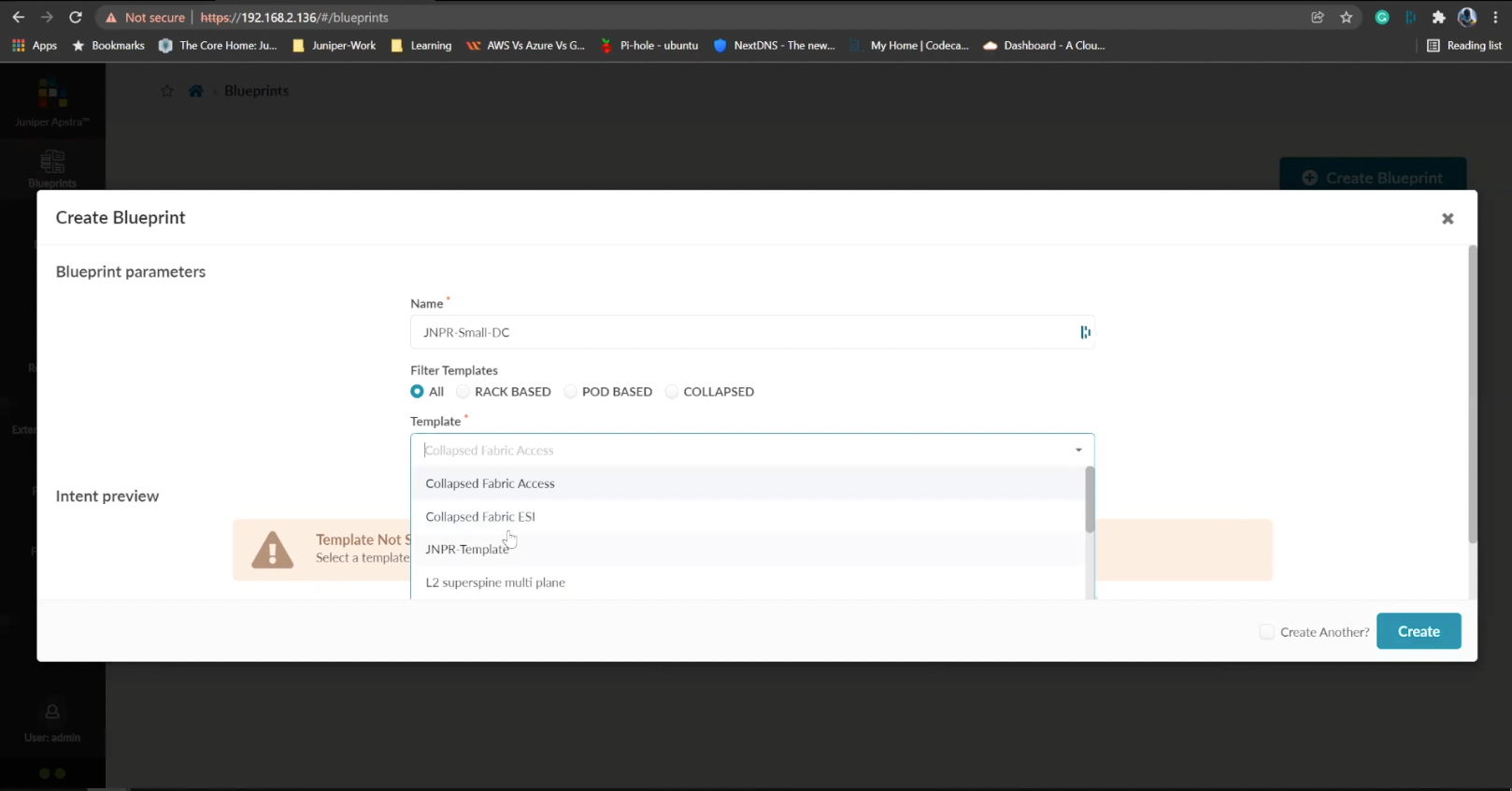
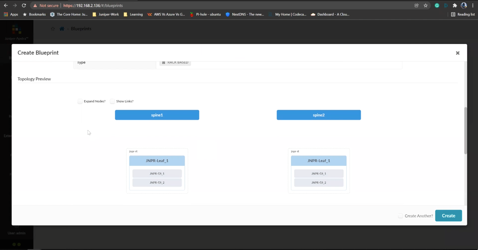
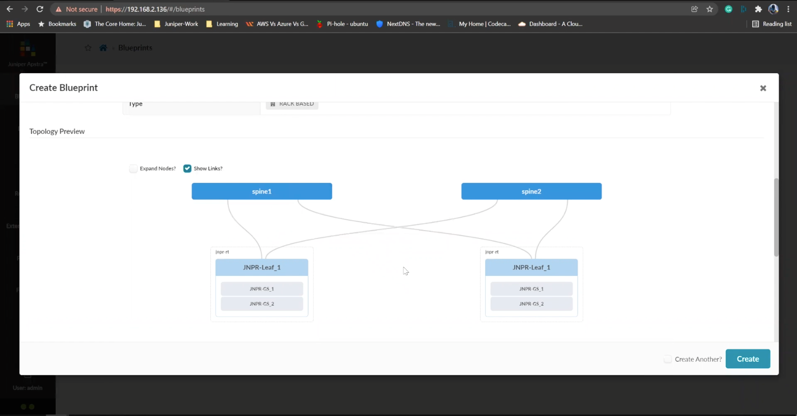
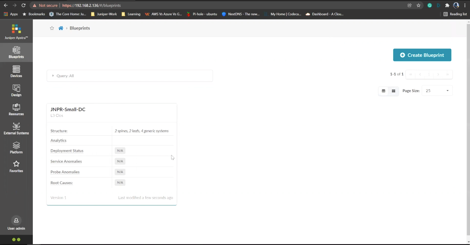
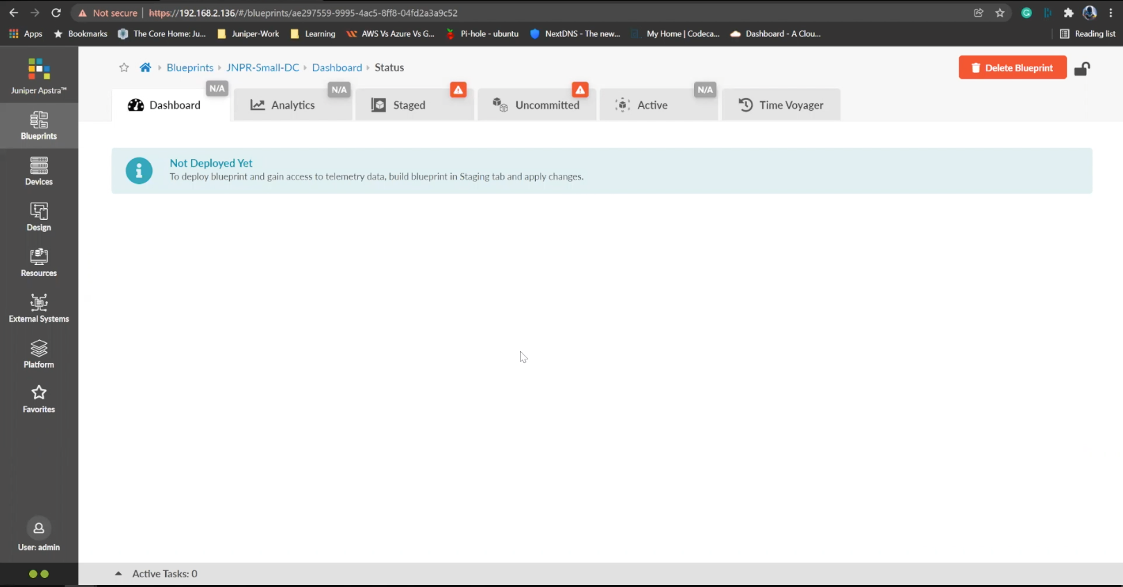
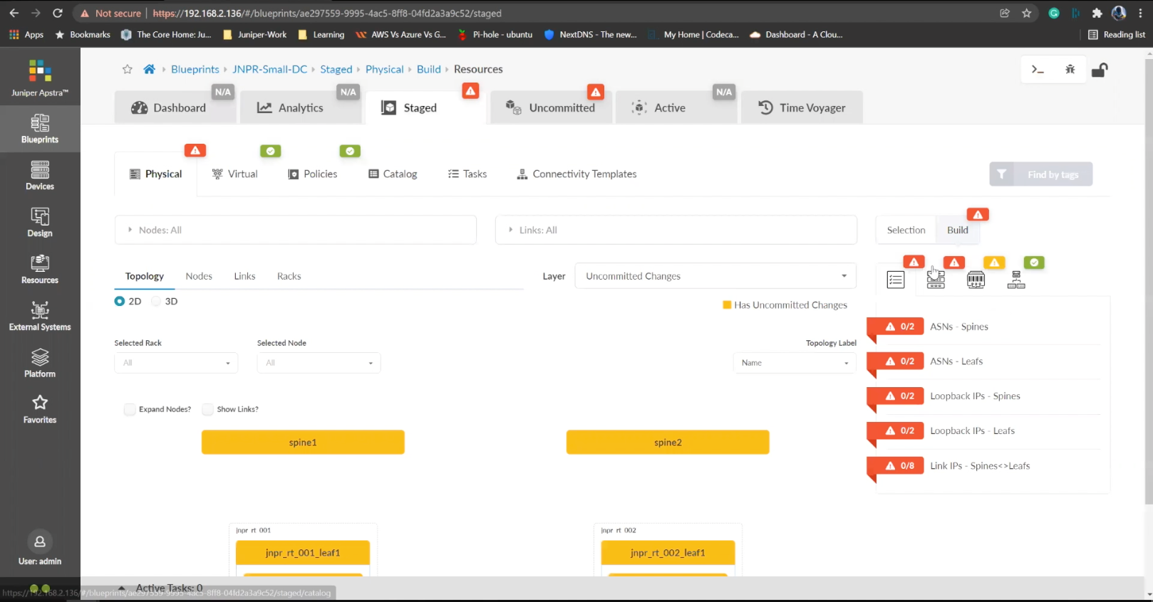
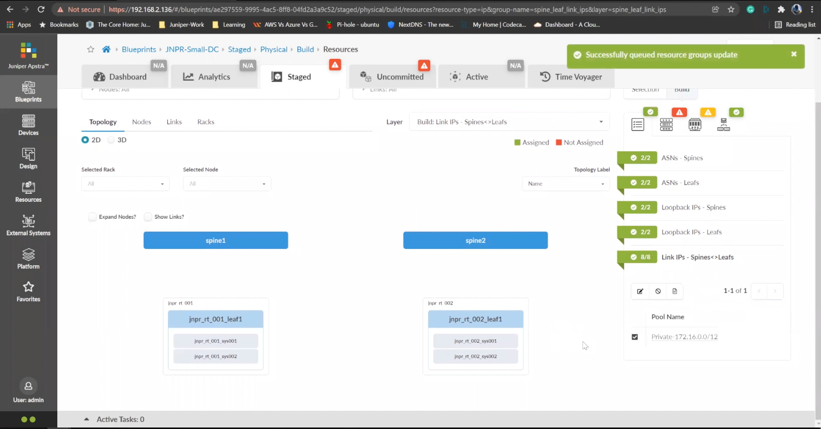
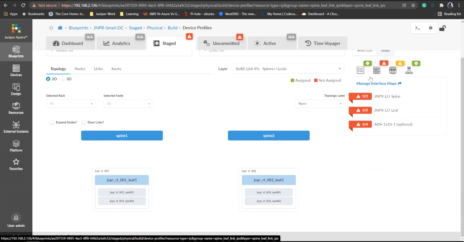
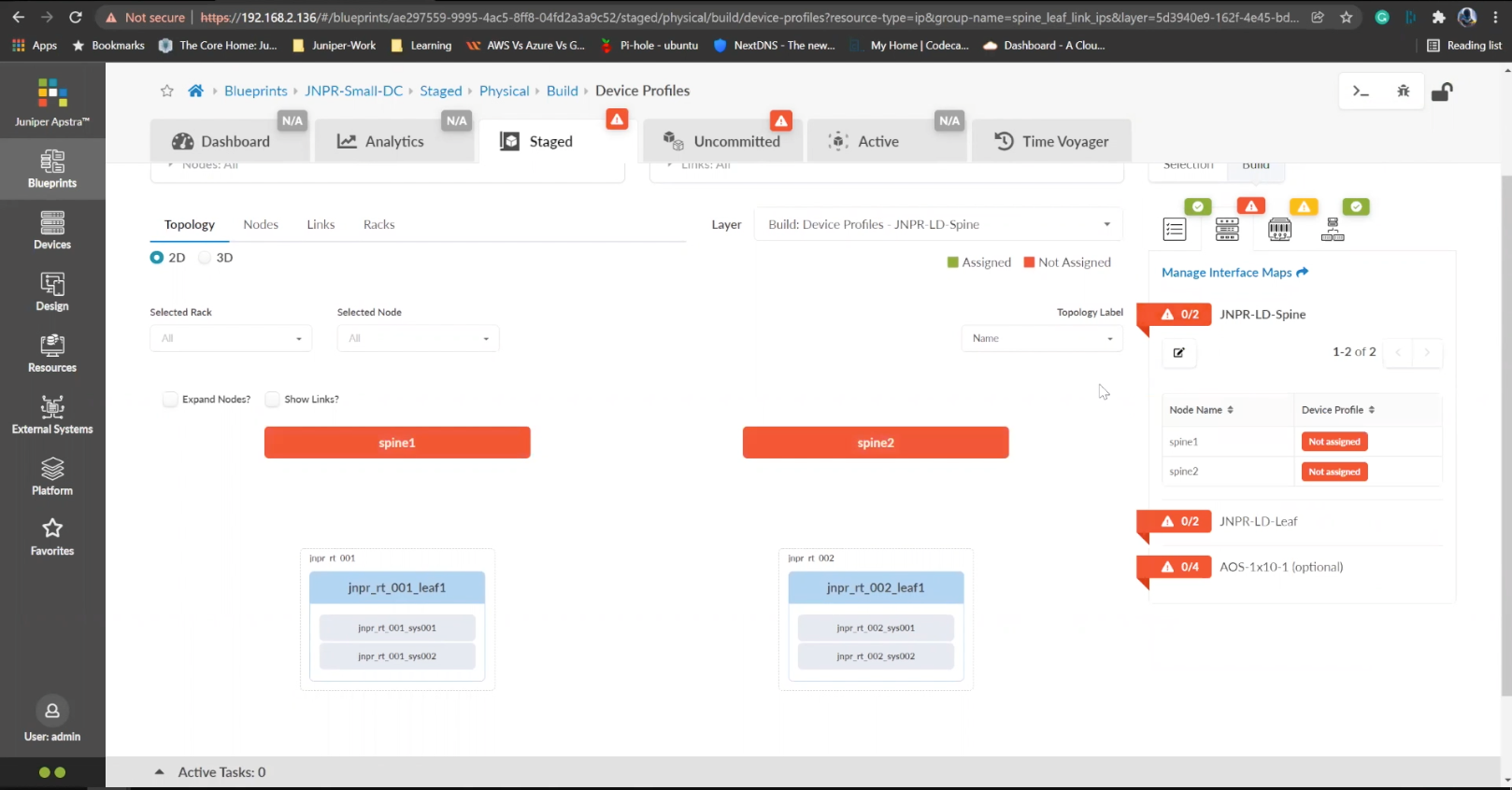
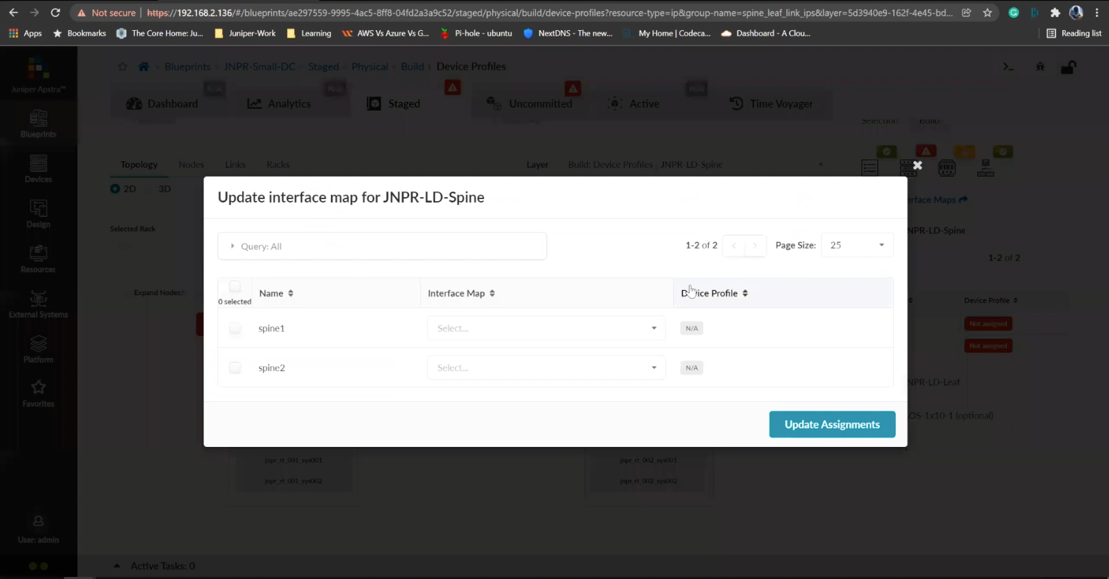
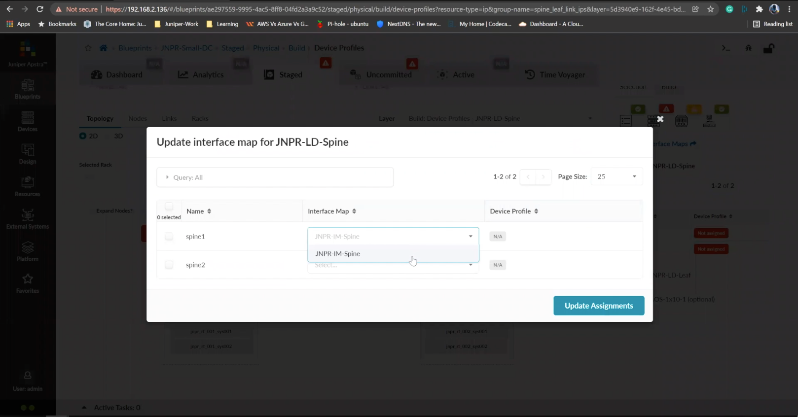
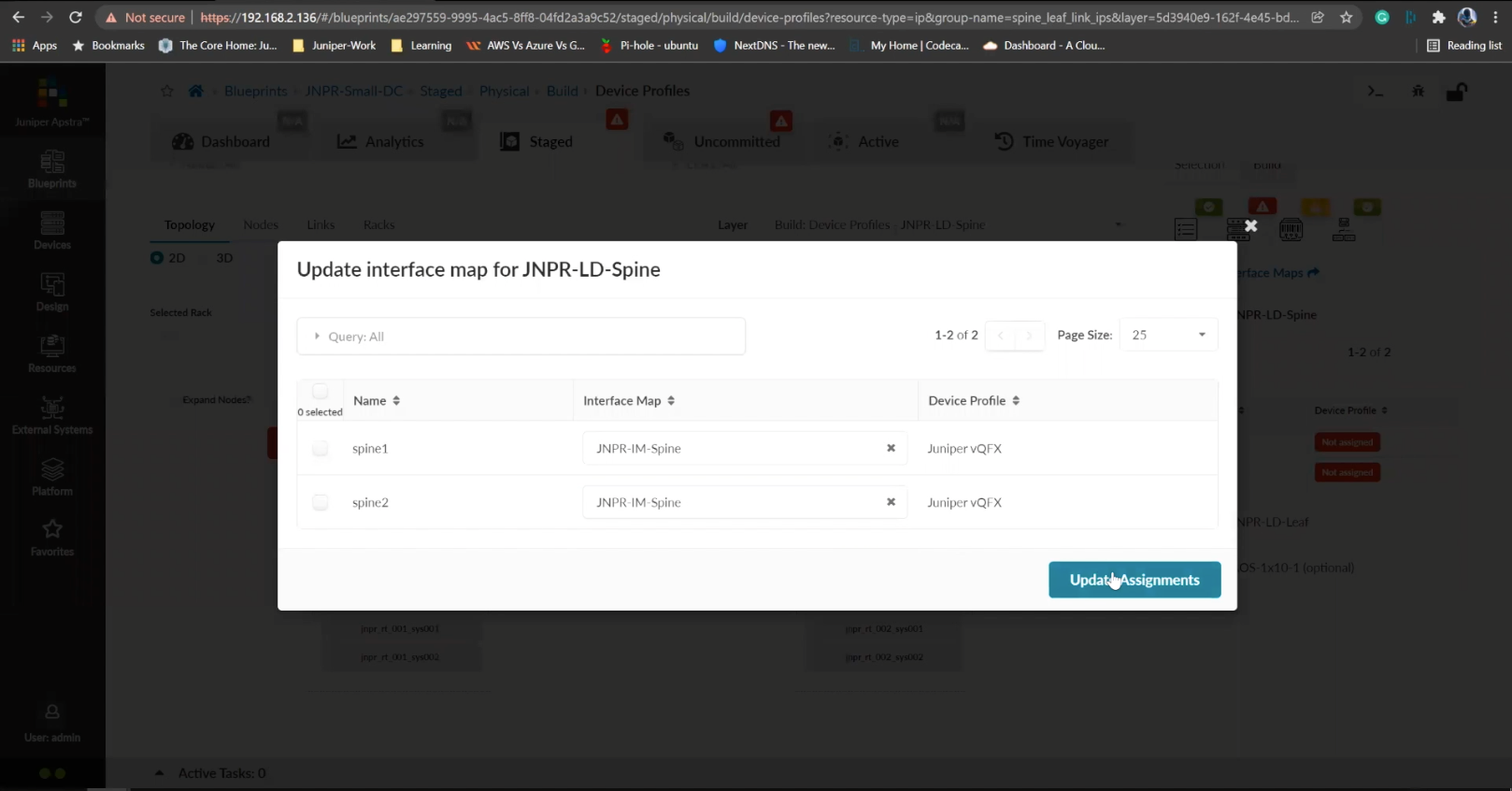
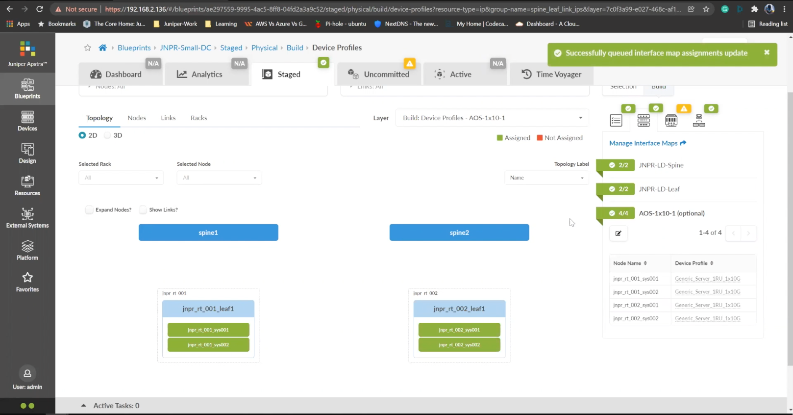
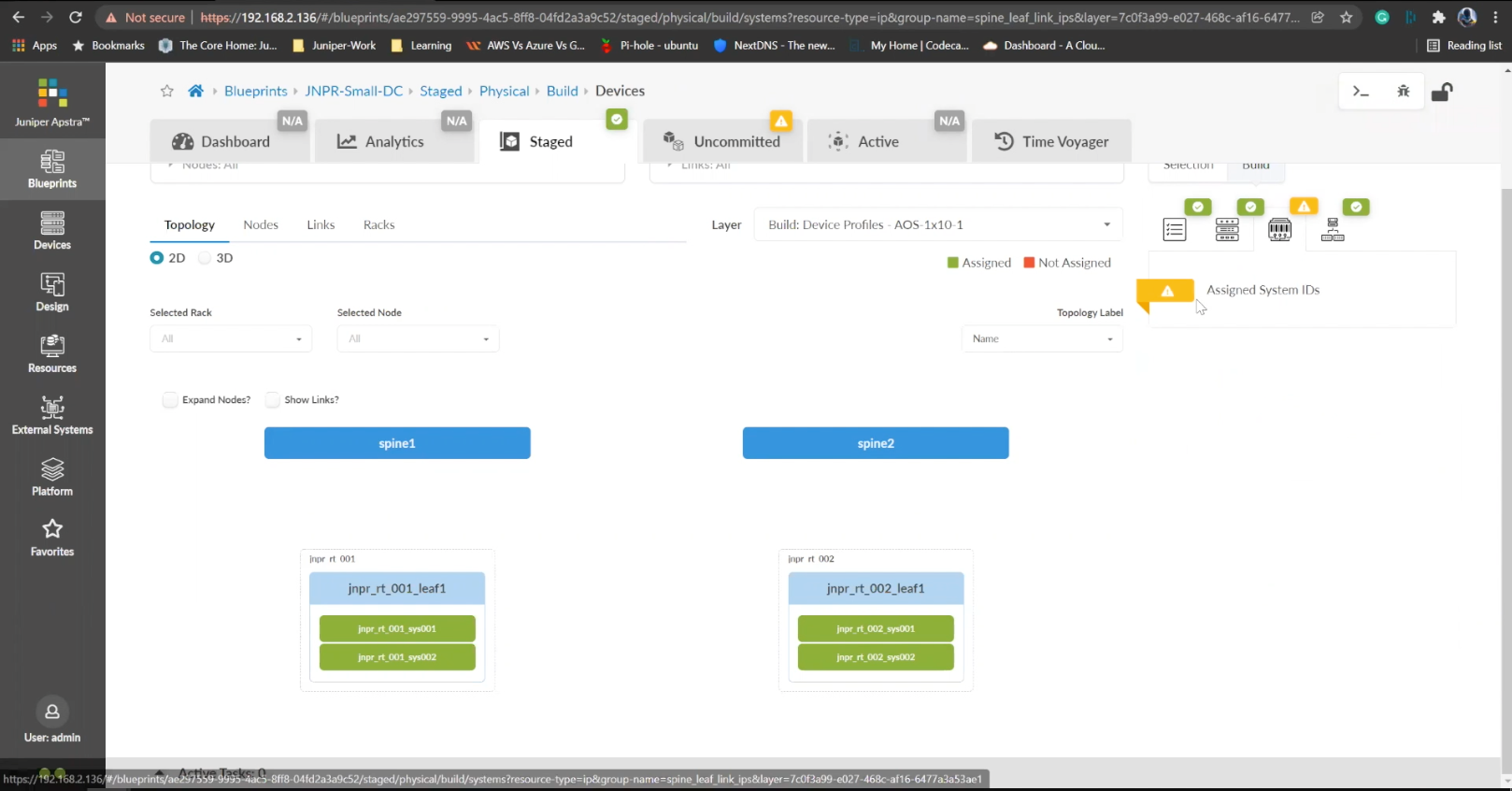
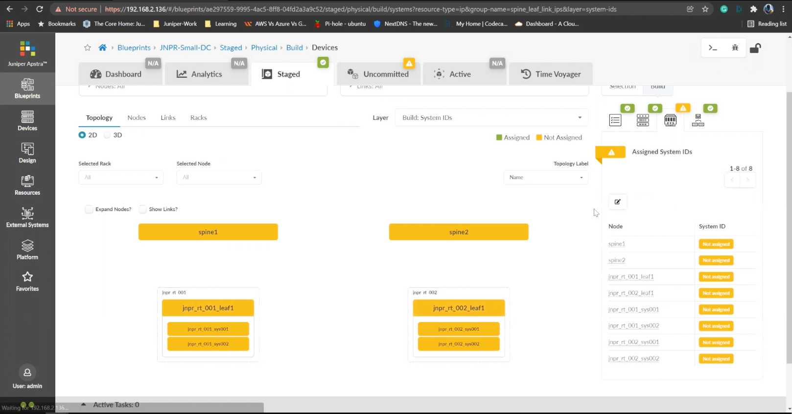
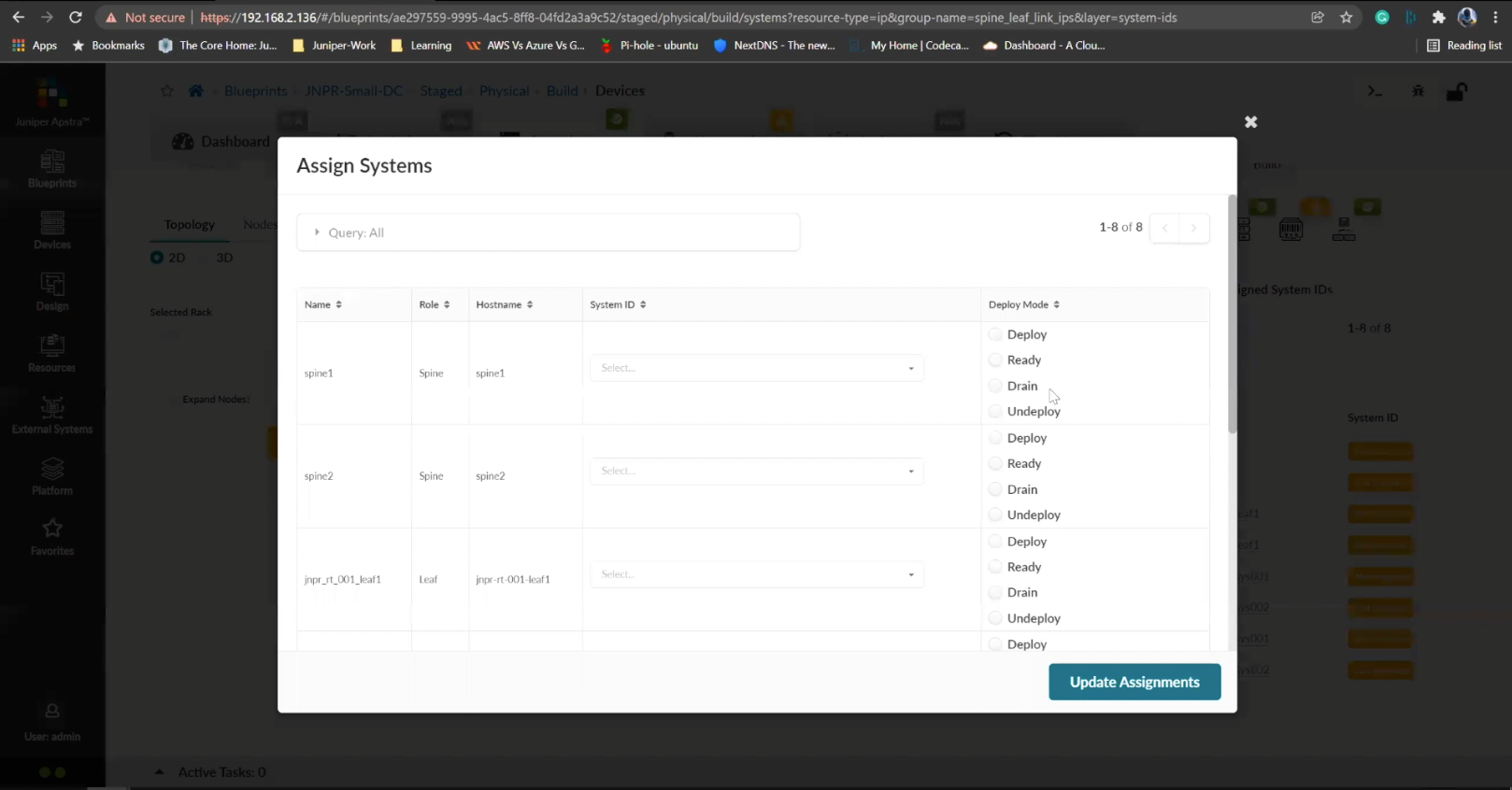
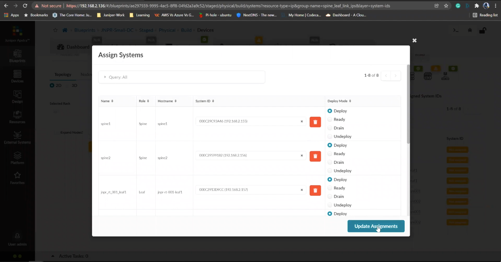
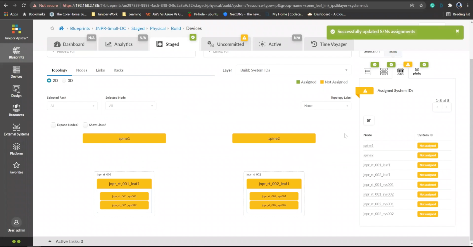
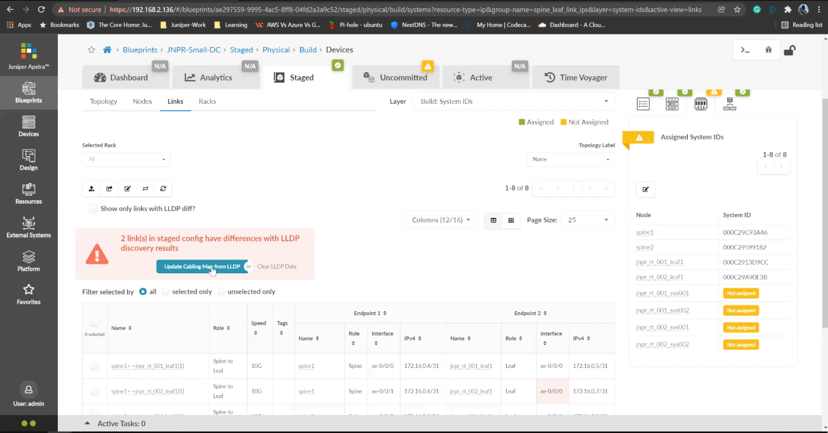
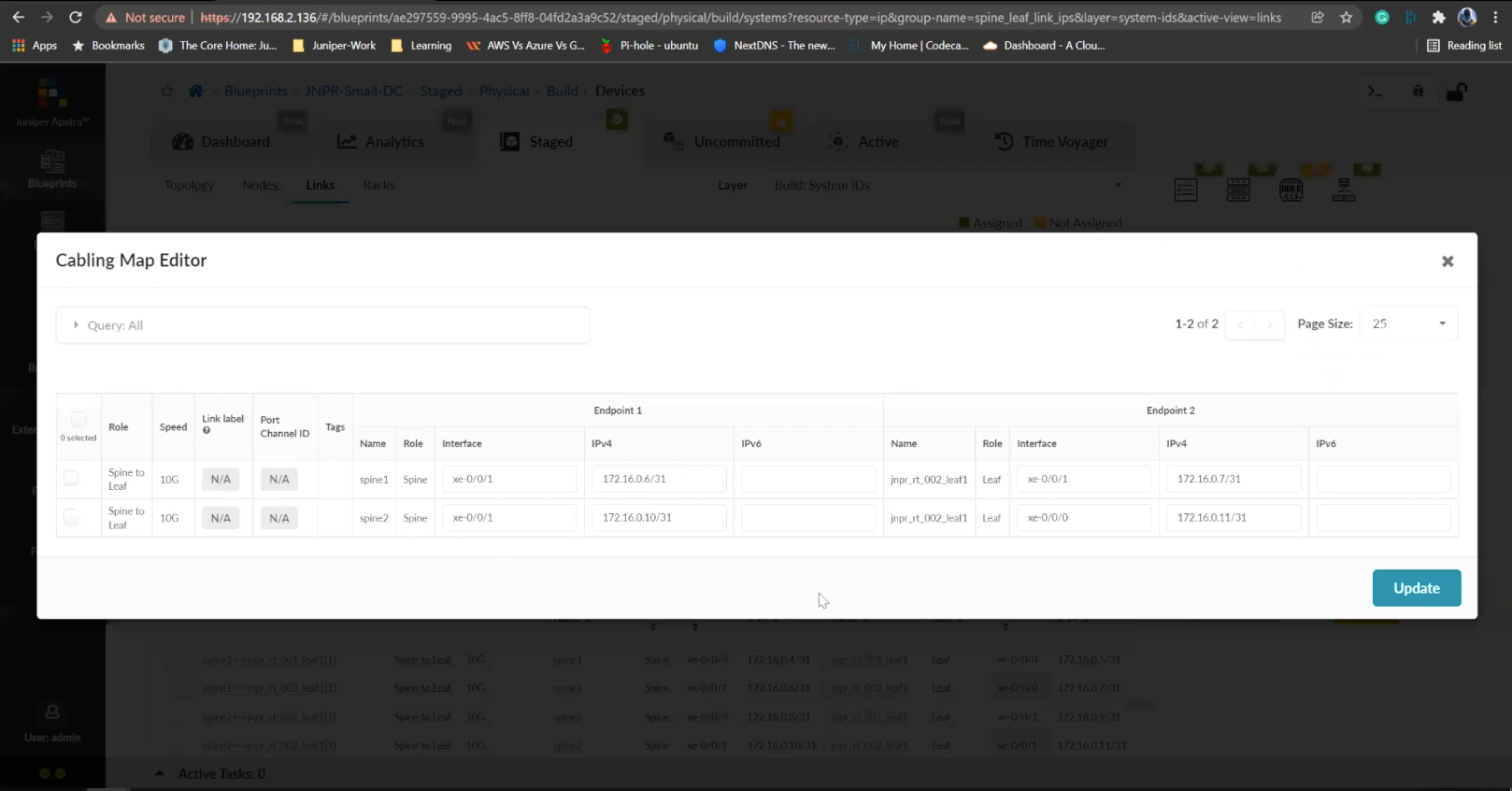
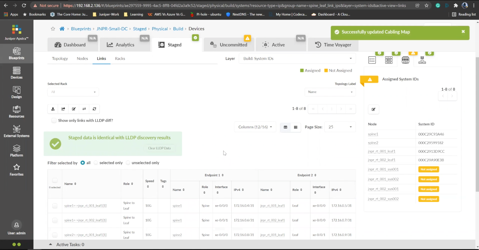
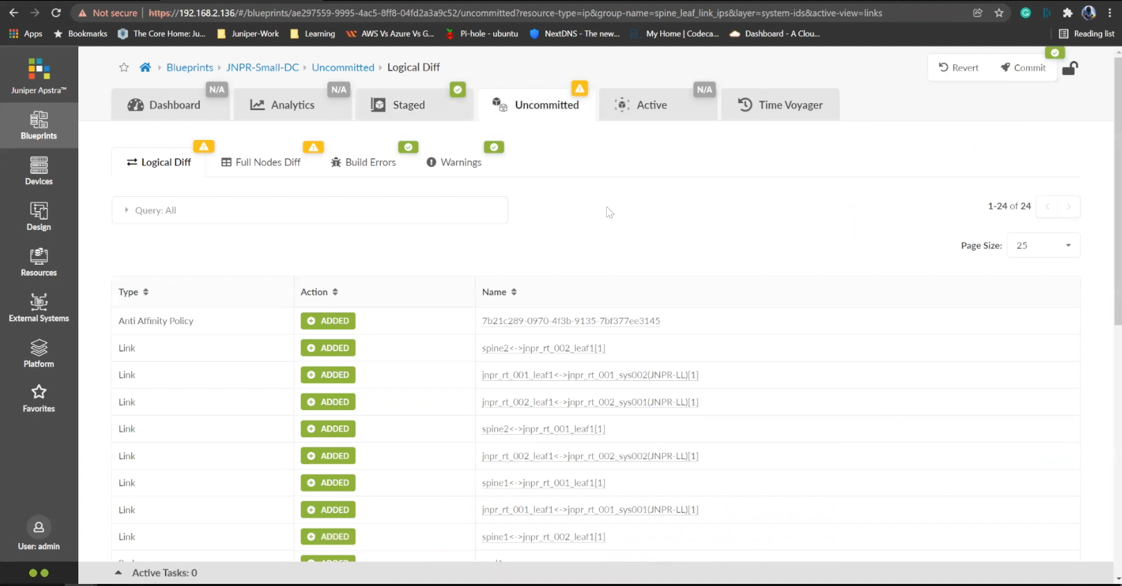
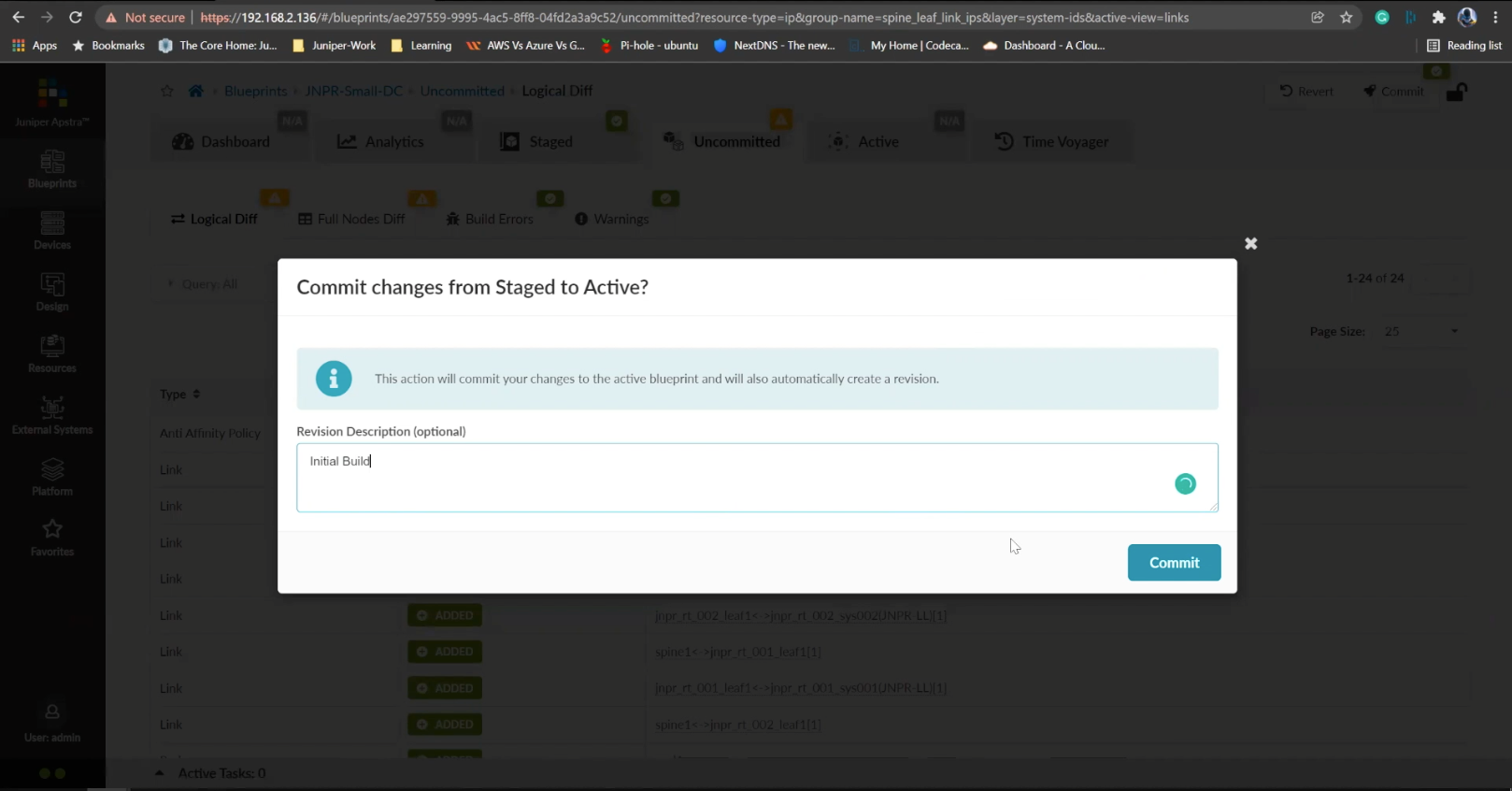